Advertisement
Quick Links
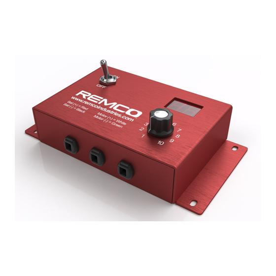
REMCO RATE CONTROLLER
Operational and Installation Guidelines
RRC PUMP CONTROLS:
15 AMP - RRC15-XX
35 AMP - RRC35-XX
Notes
DO NOT operate the controller without a fuse.
y
DO NOT use a fuse with a current rating that is higher than the full
y
load current specification of the controller. The controller is supplied
with an inline fuse that matches the full load current specification.
DO NOT use a battery charger to power the controller. The battery
y
charger may become damaged and/or prevent the controller from
functioning properly.
Installation and Operations
1. Mount the controller in a location where the power switch, speed adjustment knob, and indicator light or digital pressure display can be easily
accessed or viewed from inside the cabin of the vehicle. Use four pan head screws to securely mount the controller on a flat surface using the
four mounting holes on the case.
2. Connect the Black (-) wire to negative battery and the Red (+) wire to positive battery. For the full load current with wire lengths up to 20 feet
use a minimum of 14 AWG (12 AWG recommended) wire for the 15 Amp model and a minimum of 10 AWG for the 35 Amp model. If the power wires
are connected backwards the reverse polarity protection will cause the inline fuse to blow.
3. Connect the White (+) controller wire to the Remco pump Red (+) wire and the Green (-) controller wire to the Remco pump Black (-) wire. For
the full load current with wire lengths up to 20 feet, use a minimum of 14 AWG (12 AWG recommended) wire for the 15 Amp model and a minimum
of 10 AWG wire for the 35 Amp model. DO NOT connect the Green (-) controller wire to negative battery! It must only be connected to the pump
negative wire.
4. The Run/Hold feature allows a connected implement switch to enable or disable the pump when the implement is raised or lowered. When the
implement switch is closed the controller motor output is enabled. The indicator light on the Non-Digital models will be on. The pressure display
on the Digital models will be on and showing the transducer pressure. When the implement switch is open the controller motor output is disabled.
The indicator light on the Non-Digital models will be continuously flashing two times per second. The pressure display on the Digital models will
be continuously flashing the transducer pressure two times per second.
a.) If using a Hall-effect sensor, disconnect the dummy plug and connect the Hall-effect sensor plug to the controller.
b.) If using a normally open whisker switch, cut the wire loop on the dummy plug and connect the whisker switch wires to the dummy plug wires.
It is recommended to use 18-20 AWG wire for these low current signal wires. DO NOT connect either of these wires to negative battery! These
wires must only be connected to an electrically isolated switch.
5. The Digital models feature a digital pressure display that shows the pressure in psi transmitted by a pressure transducer.
a.) Install the pressure transducer into a female ¼" NPT port on the output line of the pump.
b.) Connect the wiring harness plug to the pressure transducer.
c.) Route the wiring harness to the controller and connect the wiring harness to the 3-pin connector.
d.) Connect the 3-pin connector to the controller pressure transducer connector.
6. Lift up on the actuator of the locking toggle power switch and move it to the on position to enable the controller. The indicator light will illuminate
on the Non-Digital models, and the digital pressure display will illuminate and show the pressure in psi transmitted by the pressure transducer on
the Digital models.
7. Turn the speed adjustment knob clockwise to increase the speed of the connected motor. The maximum clockwise setting of 10 results in the
maximum motor speed. The minimum counter-clockwise setting of 1 results in the minimum motor speed.
8. If a fault condition occurs during startup or operation of the controller a fault code will be shown by flashing the indicator light a specific number
of times on the Non-Digital models or by displaying numeric fault codes on the Digital models. If there are multiple active faults the controller will
continuously cycle through the faults codes until the power switch is cycled off and back on.
www.remcoindustries.com
Verify that the pump's maximum current draw is less than or equal
y
to the controller's rated full load current. The maximum current draw
specification is typically printed on the pump's label.
DO NOT mount the unit near other devices that generate a large
y
amount of heat or are sensitive to higher temperatures. Continuous
operation at high load current will cause the aluminum case to get
very warm. It is recommended to mount the unit horizontally and to
provide adequate airflow around the unit.
Rate controller Manual - 2023
Advertisement

Summary of Contents for Remco RRC15 Series
- Page 1 3. Connect the White (+) controller wire to the Remco pump Red (+) wire and the Green (-) controller wire to the Remco pump Black (-) wire. For the full load current with wire lengths up to 20 feet, use a minimum of 14 AWG (12 AWG recommended) wire for the 15 Amp model and a minimum of 10 AWG wire for the 35 Amp model.
- Page 2 Digital Model Digital Pressure Power Switch Display Speed Adjustment Knob 4x Mounting Holes Run/Hold (+) = White Battery (+) = Red Run/Hold (-) = White Battery (-) = Black Sensor (+) = Red Motor (+) = White Sensor (-) = Black Motor (+) = Green Sensor Signal = White Non-Digital Model...
- Page 3 Troubleshooting Guidelines Issue/Condition Solution • Verify the inline fuse is installed in the inline fuse holder and is not blown. Replace with the appropriately rated fuse if necessary. • Power switch is on but indicator light or • Verify that the Battery (+) voltage is between 8-18VDC. display is not on •...
- Page 4 This is a Limited Warranty. It covers the product only and the extent of the coverage is limited to the terms apply: For all REMCO products, the warranty will last for a period of one year from date of cost of the product. As the manufacturer has no control over shipping, handling and manufacture, or (1) year use with proof of purchase, not to exceed (2) years in any event.
Need help?
Do you have a question about the RRC15 Series and is the answer not in the manual?
Questions and answers