
Subscribe to Our Youtube Channel
Summary of Contents for First COOL-PAK ECE Series
- Page 1 Installation, Operation, & Maintenance Manual IOM 7509 Rev. A 03/22 ECE, EHE SERIES Vertical Packaged Air Conditioning / Heat Pump Units...
-
Page 2: Safety Considerations
COPYRIGHT First Co. works to continually improve its products and as a result, it reserves the right to change design and specifications without notice. The warranty may be void unless the Startup & Performance Checklist is completed and returned to the warrantor. If the COOL-PAK unit is not installed properly the warranty will be void as the manufacturer can’t be held accountable... - Page 3 General Recognize safety information. This is the general safety-alert symbol When you see this symbol on the unit and in instruction manuals, be alert to the potential for personal injury or damage to equipment. The lightning bolt symbol signifies an electrical shock hazard. WARNING: This WARNING signifies general hazards which could result in personal injury or death.
-
Page 4: Packing List
General in the United States, as well as any state laws and local codes. Local authorities having jurisdiction should be consulted before installation is made. Such applicable regulations take precedence over the general instructions contained in this manual. NOTE: HW Units- State of MA.-248 CMR code of the state of MA. requires a pump timer (60 seconds on every 6 hours). -
Page 5: Wall Sleeve Installation
LOCATION LOCATION The COOL-PAK is designed for through-the-wall installation. The interior portion of the unit is surrounded by a closet with a rear access (Figure.1). The vertical discharge allows for ducting to the top of the room for best air circulation and elimination of cold drafts on occupants. -
Page 6: Rear Installation
WALL SLEEVE INSTALLATION Small Sleeve Closet Installation and Dimensions FIGURE 2. Notes: 1. Sleeve rough-in opening is 44”(H) x 21-5/8”(W). Grille width is 22” or 22-3/4” 2. Bottom of opening should be approx. 6” above floor level. 3. Minimum 3” of clearance is required on all sides of the Unit must line up with door Exterior COOL-PAK unit. - Page 7 WALL SLEEVE INSTALLATION ACCESS PANEL DIMENSIONS FIGURE 3. Access Panel Dimensions DESCRIPTION PART LOUVERED 931-11 87” 84” 31” 28” NON-LOUVERED 931-12 87” 84” 31” 28” LOUVERED 931-13 82” 79” 31” 28” NON-LOUVERED 931-14 82” 79” 31” 28” LOUVERED 931-15* 87” 84”...
-
Page 8: Installation Precautions
• Always use proper tools and equipment. • No wiring or other work should be attempted without first ensuring unit is completely disconnected from the power source and locked out. Always verify that a good permanent, uninterrupted ground connection exists prior to energizing any power sources. - Page 9 COOL-PAK INSTALLATION COOL-PAK INSTALLATION Insulation is installed in indoor equipment to provide a barrier between outside air conditions surrounding the unit and the varying conditions inside the unit. If the insulating barrier is damaged, the surrounding ambient air will affect the inside surface temperature of the cabinet.
- Page 10 COOL-PAK INSTALLATION NOTE: Inspect the sleeve seal, which is supplied with the sleeve, to ensure that it is properly secured and aligned (Figure. 4). Use a high grade non-hardening sealant to close any gaps that may exist between the seal and the wall of the sleeve.
-
Page 11: Air Distribution
AIR DISTRIBUTION AIR DISTRIBUTION Install ductwork onto unit discharge and ensure that the connection is leak free. A flexible boot connection may be desirable to provide more noise elimination, convenient installation and removal of the COOL-PAK unit. All duct work must be installed in accordance with National Fire Protection Association Codes 90A and 90B. -
Page 12: Condensate Drain
PIPING NOTE: Coil freeze protection is recommended for applications where the COOL-PAK is located in ambient air locations or within structures that may be unoccupied during freezing conditions. Consult the factory for additional information. CONDENSATE DRAIN The COOL-PAK is designed so that the wall sleeve is the principle drain pan. Drain tubing is factory installed which drains evaporator condensate through the bottom of the unit which then is allowed to drain into the wall sleeve pan. -
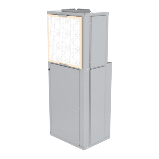
Page 13: Air Filter
AIR FILTER AIR FILTER All indoor return air must be filtered. The preferred methods are: Use the factory supplied filter kit which attaches to the inlet of the evapora- tor. Use the filter kit supplied with the access panel which accepts a 20 inch x 20 inch x 1 inch throwaway type filter. - Page 14 SYSTEM CHECK COOL-PAK (EHE) HEAT PUMP UNITS Set thermostat system switch to “Off” position and fan switch to “Auto” posi- tion. Apply power to the EHE unit. NOTE: The EHE employs a random reset timer which delays unit operation up to 60 seconds following initial power application.
-
Page 15: Maintenance
MAINTENANCE MAINTENANCE If servicing or major repairs are required, the complete unit can be removed as follows: Disconnect the electrical power circuit supplying the unit. Remove line and low voltage wiring from unit. Remove rear access panel. Remove supply duct from top of unit. Slide unit back out of sleeve. - Page 16 Manufactured by: 8273 Moberly Lane Dallas, TX 75227 www.firstco.com The manufacturer works to continually improve its products and as a result, it reserves the right to change design and specifications without notice. ©2022 First Co., 8273 Moberly Lane, Dallas, TX 75227...
Need help?
Do you have a question about the COOL-PAK ECE Series and is the answer not in the manual?
Questions and answers