Table of Contents
Advertisement
Quick Links
Advertisement
Table of Contents

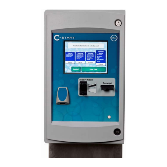
Summary of Contents for Unitec C-Start
- Page 1 C-Start Installation Manual Unitec 443-561-1200 • www.StartwithUnitec.com...
- Page 2 C-START INSTALLATION MANUAL This manual provides installation instructions for the C-Start. It includes site planning, site preparation, the mechanical installation of the C-Start and the electrical wiring of the unit. When calling for assistance, you must have the following information available:...
-
Page 3: Table Of Contents
3.5.3 Intercom Adjustments ........................12 3.5.4 Connection Overview .........................12 System Startup ..........................13 System Test...........................13 Appendix A - POS Interface Option....................15 Appendix B - C-Start Networking ......................16 Appendix C – Terminating Ethernet Cables ..................18 Document Number: CST1001 Document Name: C-Start Installation Manual... - Page 4 Figure 1. C-Start Position......................... 2 Figure 2. Conduit Runs ........................4 Figure 3. Straight Bases Dimensions....................6 Figure 4. C-Start Interior Connections ..................... 7 Figure 5. Neutral - Ground – Line Connections ................8 Figure 6. Wash I/O Board Connector Pinouts.................. 9...
-
Page 5: Site Planning And Preparation
C - S T A R T 1 Site Planning and Preparation This chapter provides guidelines for positioning the C-Start and preparing the site. Site preparation includes: • Determining how and where the C-Start will be mounted • Installing conduit runs and required wiring These instructions serve as general guidelines only. -
Page 6: Positioning The C-Start
C - S T A R T 1.1 Positioning the C-Start When installed at the wash entrance, the C-Start should be located at least 12 feet from the wash. For curb mount applications, the front surface of the C-Start should be even with the edge of the curb. -
Page 7: Electrical
Conduit size should be at least ¾ in. Refer to local and national electrical codes to select the proper conduit type and size. Conduit stubs should be installed to enter the C-Start base through the oblong conduit opening as shown in Figure 2 and extend at least 3” above the concrete surface. -
Page 8: Wiring Requirements
16 AWG (black/white/green) Network connection (to router) Cat 5 communications cable, 295 ft max length Wash Control Varies Per wash equipment manufacturer’s instructions Intercom (Optional) 22 AWG minimum, Qty varies by intercom model Document Number: CST1001 Document Name: C-Start Installation Manual... -
Page 9: Installation
Wire Strippers (capable of 10 – 22 AWG wire) • Modular plug crimp tool (if CAT 5 cable needs to be terminated) • Diagonal Cutters • Needle Nose Pliers • Dual-plane Level Document Number: CST1001 Document Name: C-Start Installation Manual... -
Page 10: Base Installation
Note: wiring requirements. The C-Start bases are available in (2) heights as shown in the illustration below. This document describes the procedure for installing the straight base. Angled bases are also available and they are supplied with a manual addendum (MN1001), which provides additional instructions. -
Page 11: Mounting The C-Start
C - S T A R T 2.4 Mounting the C-Start 1. Rest the C-Start enclosure on top of the base and feed the wires through the rectangular opening in the bottom the enclosure. This opening is partially covered by a metal plate which can be slid forward or removed completely to provide greater access. -
Page 12: Connecting Power
C - S T A R T 3.2 Connecting Power 1. Route the main power wires to the AC terminal strip on C-Start’s power panel (as shown below) and trim the wire to remove excess. Strip the insulation approximately ¼ ” on each conductor. -
Page 13: Wash Control Wiring
3.3 Wash Control Wiring 3.3.1 Overview In applications where the C-Start will communicate with the Wash Controller, the wash control wires will need to be connected to the Wash I/O Board. This board is located on the right wall of the enclosure and is shown in the picture below. The board is supplied with screw terminal plugs (not shown) installed in the green connectors to accommodate field wiring. -
Page 14: Wiring The Wash Relay Interface
To wire the wash in use and fault inputs, remove the screw terminal plug from the J18 connector and install the wires from the PLC to the appropriate pin numbers per the table below. Replace the plug in J18 when finished. Document Number: CST1001 Document Name: C-Start Installation Manual... -
Page 15: Network Cable Connection
Ethernet port. Insert the terminated CAT 5 cable into the other end of the surge protector. The facility end of the Cat-5 cable connects to one of the LAN ports on the Unitec router. Refer to 0 for details on connecting devices to the router. 3.5 Intercom Systems 3.5.1 Overview... -
Page 16: Intercom Connections
More detailed instructions on this follow. Audio: When the C-Start intercom mode is active, the audio section is floating and is not relative to ground. By default, J17-Pin 3 (SP+) and J17-Pin 4 (SP-) will always be connected to the audio section. -
Page 17: System Startup
• Washes and added services are properly configured and wash outputs are properly wired. • The wash fault (Out of Service) signal places the C-Start out of service. • C-Start Ethernet communications (through the Cat 5 cable). • Credit card processing (Note: The merchant should confirm credit card revenues are being properly deposited to their account). - Page 18 [ T H I S P A G E I N T E N T I O N A L L Y L E F T B L A N K ] Document Number: CST1001 Document Name: C-Start Installation Manual...
-
Page 19: Appendix A - Pos Interface Option
Unitec router and the C-store POS System. A 3ft Ethernet cable is included for connecting the Ethernet port of the converter to the Unitec router (see Appendix B). A standard 9-pin serial cable is included for connecting the Serial port of the converter to the C-Store POS however, some POS systems may require an alternate cable (or adapter). -
Page 20: Appendix B - C-Start Networking
A print server (for connecting a local report printer) In cases where there will be more than (4) Unitec devices on the network, an Ethernet switch will need to be added. The WAN port of the switch connects to one of the LAN ports of the Unitec router. - Page 21 3 party device connections. When a router (or modem with built-in router) is used between the Unitec router and broadband connection, it must be configured to allow external connections to and from the C-Start. The router should be configured to: •...
-
Page 22: Appendix C - Terminating Ethernet Cables
(see Warnings). For easier handling, cut the wires so that they are 3/4" (19 mm) long from the base of the jacket and even in length. Document Number: CST1001 Document Name: C-Start Installation Manual... - Page 23 The cabling jacket should also enter the rear of the jack about 1/4" (6 mm) to help secure the cable once the plug is crimped. You may need to stretch the sleeve to the proper length. Verify that the sequence is still correct before crimping. Document Number: CST1001 Document Name: C-Start Installation Manual...
- Page 24 A simple cable tester can quickly verify that information for you. Should you not have a network cable tester on hand, simply test connectivity pin to pin. Document Number: CST1001 Document Name: C-Start Installation Manual...
Need help?
Do you have a question about the C-Start and is the answer not in the manual?
Questions and answers