Advertisement
Quick Links
Advertisement

Summary of Contents for Topcon CC-100 Series
- Page 1 QUICK MANUAL LCD Computerized Chart CC-100 Series REV. 10 2012...
- Page 2 The CC-100 Series Computerized chart complies with European Medical Device Directive and bears the CE marking. Before connecting a external device to the CC-100 Series product make sure that such external equipment is in compliance with EN 60950-1 and CE marking.
-
Page 3: Intended Use
Utilisation The CC-100 Series device is a instrument for the analysis of visual acuity. The CC-100 Series device is able to execute the principal and most important visual tests: acuity, binocular vision, contrast sensitivity, and more. The entire display screen is capable to display standard visual acuity tests and dissociated tests too. - Page 4 To ensure an optimal coverage of polarized tests, align the center of LCD with the line of sight of the patient. Wear the polarized or Red/Green lenses and select in CC-100 Series a dissociated test, check the horizontal and vertical alignment until the best coverage for each eye is reached.
- Page 5 EMC Table Emission Guidance The CC-100 SERIE is intended for use in the electromagnetic environment specified below. The costumer or the user of the CC-100 SERIE should assure that it is used in such an environment. Emission Test Compliance Electromagnetic enviroment guide Group 1 The CC-100 SERIE device uses RF energy only for RF Emission...
- Page 6 Immunity Guidance CC-100 SERIE device is intended for use in the electromagnetic environment specified below. The customer or the user of the device should assure that it is used in such an environment. Immunity Test Test level Conformity Level Electromagnetic EN 60601-1-2 enviroment guide ...
- Page 7 Immunity Radio Frequency Guidance is manufactured to work in the electromagnetic environment specified below. The CC-100 SERIE operator or user should make sure it is use within those environmental conditions.. Immunity Test Test level Conformity Level Electromagnetic enviroment EN 60601-1-2 guide Portable and mobile RF Conducted RF...
- Page 8 Symbol Table:...
-
Page 9: Warning Indications And Positions
WARNING INDICATIONS AND POSITIONS For safety purposes, this equipment includes clearly labelled warnings. Use the equipment following this warning instructions. CAUTION To avoid electrical shock, do not open the instrument. Refer all servicing to only qualified personnel. WARNING Electrical shock may cause burns or possible fire. Turn the main power switch OFF and UNPLUG the power cord before replacing fuses. -
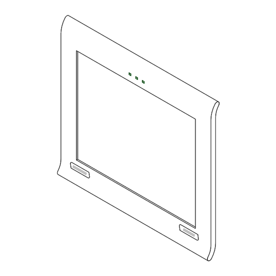
Page 10: Main Body Components
COMPONENTS MAIN BODY COMPONENTS I/R Sensor Photo Sensor Maddox Led Test Area Wall hook Wallmounting screw holes AC-3 pin Power cable... - Page 11 CC-100 SERIES STANDARD ACCESSORIES...
-
Page 12: Remote Control
CC-SERIES OPTIONAL ACCESSESORIES REMOTE CONTROL CC-Series Remote Control Batteries Remote Control (AAA Type) (only for CC-100 Series instruments) CC-100 WALL MOUNTING... - Page 13 PREPARATIONS WARNING: use appropriate screws and plugs to fix the unit to the wall. Without WALL MOUNTING With WALL MOUNTING...
- Page 14 SWITCH BETWEEN LCD Chart Projector and CV-tablet When using the new CC-100 Series device, we will find pre-installed two main charts software. The LCD Chart Projector and of course the CV-tablet. To use one instead of the other follow the steps below directly on the CC-100:...
-
Page 15: Basic Operations
BASIC OPERATIONS REMOTE CONTROL (CC-100 SERIES MODE ) Infrared led Mode selection Visual Acuity selection Mask and red-green filter functions Random Contrast Inverted Fixation point / Amsler’s grid, Schober test / Worth test Bichromatic vision tests and Polarized stereo tests (CC-100XP) - Page 16 VISUALIZATION OF A SPECIFIC SCREEN SHOT Select symbols Letters Snellen E Landolt C Numbers Drawings for Children...
- Page 17 Select Visual Acuity levels ETDRS Only the first two buttons of section can be used.
- Page 18 Masking by line, column or single cell and red-green background Vertical Mask Horizontal Mask Single Cell Mask R/G Background Casual chart generating (random function) To deactivate the function press the button again. Contrast modifying of “chart over background” Pressing the arrow buttons on the remote control the type contrast change with step 0.1. To deactivate the function press the button again.
- Page 19 Inversion To deactivate the function press the button again. Fixation point, Amsler’s grid, Worth test and Schober test If fixation led option is set to ON (see Menu section on this manual).
- Page 20 CC-100: Bichromatic monocular tests CC-100XP: Polarized balance test (see Note 1) NOTE 1 (for CC-100XP only) The drawings are only exemplificative. Red parts are seen by the right eye, green parts are seen by the left eye. The charts are all black on white.
- Page 21 Dissociated tests CC-100: Red/Green filter CC-100XP: Left/Right circular polarization (see Note 1)
- Page 22 Unpolarized tests...
-
Page 23: Special Tests
SPECIAL TESTS Contrast Sensitivity Test (First press) Choose Chart Type Choose Visual Acuity Level Start Test Use the arrow buttons for the test. The least difference of contrast distinguished from the patient is displayed on the screen. - Page 24 Sinewave Contrast Sensitivity (Second press) Choose Test Map Map Settings Start Test Map patterns and settings Enter into Map Settings sub menu to change options for selected Test Map.
- Page 25 Each Test Map has a pattern you can edit from Edit Map function. Test Map Contrast levels Frequency levels Map 1 Map 2 Map 3 Use the arrow buttons for the test, the "none" key (17) must be pressed for no answer Displayed image Arrow button to press...
- Page 26 A graph will be visualized. The area of normality is underlined in green.
- Page 27 Pseudoisochromatic Test Test Procedure (ON/OFF) Sample plates (ON/OFF) Start Test Ask the patient to recognize three different symbols hidden between dots. Testing without test procedure Use right arrow button to go to the next plate. Use left button to go to the previous plate. Up and down arrow plate change the symbol inside the same plate.
- Page 28 Symbol in upper left position Symbol in upper right position Symbol in bottom left position Symbol in bottom right position At the end of the test with test procedure a table will be presented.
- Page 29 FIXATION TARGETS Images and movies are located into 4 different groups. If you use the USB archive too, also the groups stored in the USB pendrive are shown. Use this menu item to refresh the group list, adding groups archived on USB.
- Page 30 Movies Play the movies. Use arrows to manage movies.
- Page 31 Previous movie Replay / Go back Continue / Go ahead Next movie How to configure the USB pen drive to archive additional images and/or movies Format USB pen drive in FAT32 file system format In the device root, create a folder called “images” ...
- Page 32 MKH SEQUENCE (see Note 1) Use arrows to select chart. Previous chart in sequence Next chart in sequence Use R/L button to swap right and left eye.
- Page 33 LIGHT Screen illumination. MENU General Settings Language Language selection.
- Page 34 Kids Chart Types (CC-100 Series / KB-50) Chart A Chart B1 Chart C Distance Distance patient-display. Mirror...
- Page 35 I/R Devices Select a working mode for each of the 4 channels. Serial Device Connect the Topcon CV-5000 by serial connector. For the COM port baud rate, see the Technical Settings. VA Background Regulation Regulate the brightness of the background...
- Page 36 Red Level Regulation Set the red tone parameter of the screen to be used with the red-green filter. Green Level Regulation Sets the green tone parameter of the screen to be used with the red-green filter. Light Sensor Determine if the environment illumination is correct. Fixation Led Enable or disable the fixation led when using Maddox test.
- Page 37 Technical Settings Upgrade To upgrade the CC-100 Series Device software you will receive a compressed zip file. It contains only 2 files: Upgrade.exe a big file with extension .UPG; its name tells you the version of that upgrade (for example: CC-100 3.3.1.UPG or CC-100XP 3.3.1.UPG)
- Page 38 Configure Network Network settings. ONLY FOR SPECIFIED MODELS. Serial COM port baud rate Serial COM port baud rate setting. Settings: Reset to Default Reset to default settings. Exit It terminates the software.
- Page 39 CONFIGURE NETWORK ONLY FOR SPECIFIED MODELS. “Standalone” Mode Use the device as stand-alone. No network use. “Network” Mode Use the device as part of a network (PC). The system configures the network automatically.
- Page 40 Server search (PC with communication software installed). Server selection.
-
Page 41: Maintenance
MAINTENANCE Fuse change of the CC-100 Series Make sure that the power switch of the main body is off and the power cable is unplugged. Fuse’s types Fuse’s type Fuse’s value Power supply voltage 220 – 240 V 20 x 5 mm... - Page 42 Battery change of the CC-100 Series remote control Remove the battery cover, insert new 1.5V batteries (type AA) and replace the cover. Change of the channel setting of CC-100 Series remote control Remove the battery cover from the back of the remote control.
Need help?
Do you have a question about the CC-100 Series and is the answer not in the manual?
Questions and answers
chart is not changing
The chart may not be changing on the Topcon CC-100 Series due to incorrect use of the remote control or buttons. To change plates or symbols, the correct arrow buttons must be used: the right arrow moves to the next plate, the left arrow goes to the previous plate, and the up/down arrows change the symbol within the same plate. If these are not functioning, the remote control may require new batteries or proper pairing.
This answer is automatically generated