Table of Contents
Advertisement
Quick Links
Advertisement
Table of Contents
Troubleshooting

Summary of Contents for JEWEL Baby Lock
- Page 1 Baby Lock Service Manual Provisional ...
-
Page 2: Table Of Contents
Baby Lock Jewel Service Manual Table of Contents About the Baby Lock Jewel Quilting Machine ..............4 About the Manual ........................4 Service Manual General Rule ....................4 General Specifications ......................5 Assembly Torque Specification ....................5 Lubrication of the Hook ......................6 General Observation of the Front Frame Cover, Mast and Hand Wheel...... - Page 3 Operation Problems: ......................37 Stitch Regulator – Methodical Check ................... 38 Stitch Regulator Trouble shooting:..................39 Setup Errors: ........................39 Operation Errors: ......................39 Mechanical Problems:....................... 39 Electronic Problems: ......................39 LCD Screen Operation ......................40 © Baby Lock, all rights reserved...
-
Page 4: About The Baby Lock Jewel Quilting Machine
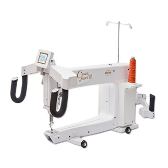
The Baby Lock Jewel Quilting Machine utilizes high-tech electronics and an innovative touch-pad user interface to offer greater functionality and ease of operation to home quilters than ever before conceived in the quilting industry. The Baby Lock Jewel Quilting Machine is a high quality machine that incorporates very robust design features and is very easy to service. -
Page 5: General Specifications
3. 6mm Allen Socket Head Cap Screws Class. 8.8 @ 9.9Nm. • An exception must be observed here since the screws are considered soft jointed and shallow threaded and are used externally. It is therefore advised that this torque specification not exceed 6Nm. © Baby Lock, all rights reserved... -
Page 6: Lubrication Of The Hook
The Spool Stand (mast) should be adjusted so that the eyelet loops are centered directly over the spool pins. • If a correction is necessary, loosen the jam nut, reposition and tighten the jam nut. Figure 2 © Baby Lock, all rights reserved... - Page 7 #3 flat-slot screw driver until the knob has adequate resistance to keep its setting. • Check that the take-up spring is positioned to 11:00. if not loosen (2mm handle Allen) and rotate split shaft. © Baby Lock, all rights reserved...
-
Page 8: Replacement Of Cover
Note 3: After installing the cables through the service hole on the front cover, carefully take out any excess cable through the hole and fold inside of the pod covers. This will prevent any pinching or © Baby Lock, all rights reserved subsequent damage to the cables by moving parts. -
Page 9: Removal Of The Front Cover
3. Remove the “C-pod” by unscrewing the 4 screws “C” in Figure 8. (#2 Phillips screwdriver) Figure 8 4. Carefully unplug the cables from the C-print and pod. Be careful not to touch the C-print. Figure 9. See plug configuration on page 8. © Baby Lock, all rights reserved Figure 9... - Page 10 7. Separate the Front Frame Cover. Make sure the take up lever does not get caught in the frame slot. Note: If the frame cover is not easily removed, loosen the front base plate screws. (5mm handle Allen) © Baby Lock, all rights reserved...
-
Page 11: Machine Cross Section
Baby Lock Jewel Service Manual Machine Cross Section © Baby Lock, all rights reserved... - Page 12 Main Timing Pulley Figure 14 FIRST SCREW, FIRST POSITION RULE: The first screw or first position is ALWAYS located 120° apart in the direction of rotation from the second screw or second position. © Baby Lock, all rights reserved...
- Page 13 Hand wheel screw – inside frame (3mm handle Allen) Drive pulley screws (2.5mm handle Allen) Figure 15 Transmission gear & pulley screws – (2.5mm handle Allen) Figure 16 Hookshaft gear screws (2.5 handle Allen) Figure 17 © Baby Lock, all rights reserved...
-
Page 14: Axial Play Check And Adjustment
Remove the play by loosening the hook shaft thrust collar and adjusting out any axial play as shown in Figure 22. (Note: No shaft flat is located here.) Figure 20 Figure 22 © Baby Lock, all rights reserved Figure 21... -
Page 15: Adjusting The Base Plate Feet And Rollers
If a correction is necessary: • Slightly loosen the front base plate screws. • Shift the front base plate until the front and rear wheels are equidistant as shown in Figure 25. Figure 25 © Baby Lock, all rights reserved... -
Page 16: Adjusting The Motor Belt Tension
If correction is necessary: • Loosen the motor frame screws 1,2,3 and 4 shown in figure 27 Figure 26 Figure 27 © Baby Lock, all rights reserved... -
Page 17: Adjusting Transmission Gear Lash (Play)
NOTE: The transmission housing is pushed to the right towards the hand wheel end of the machine, until flush with the machined edge while being adjusted. • Tighten the two transmission housing screws. • NOTE: Improper adjustments of this setting will cause timing and noise problems. © Baby Lock, all rights reserved... -
Page 18: Adjusting The Timing Belt Tension
Loosen the idler pulley screw and locknut – the bracket has an elongated hole in the motor hosing for idler adjustment. (5mm Allen tool and 10mm wrench) • Adjust the idler pulley in or out until the timing belt has the proper tautness. © Baby Lock, all rights reserved... -
Page 19: Adjusting The Presser Foot (Sewing Foot)
Tighten the jam nut. (clamp, 8mm open end wrench Note: Under NO circumstance loosen or tighten the jam Figure 30 nut without HOLDING the sewing foot as indicated © Baby Lock, all rights reserved... -
Page 20: Needle Position, Check, & Adjustment
If a correction is necessary, loosen screws F, H, (2mm handle Allen) and G (3mm handle Allen). • Loosen screw D (3mm handle Allen) and back off screw E (2mm handle Allen). Figure 33 © Baby Lock, all rights reserved... -
Page 21: Adjustment Of The Loop Lift And Needle Distance
(needle distance). Figure 36 See note next page. Figure 37 A & B © Baby Lock, all rights reserved... - Page 22 Rotate the basket 180 degrees until large cutout is up towards needle as shown in figure 40 (you will now need to hold the basket in that position - see important note above) Figure 40 © Baby Lock, all rights reserved...
-
Page 23: Adjusting The Needle Bar Height
If this happens, do not run the machine. Remove the front frame cover, reassemble the needle bar to the needle bar driver and readjust. Figure 42 © Baby Lock, all rights reserved... -
Page 24: Adjustment Of The Stop Finger
Loosen screw A, in Figure 43 and adjust the stop finger so the proper clearance is achieved as Figure 43 shown in Figures 43 and 44. • Tighten screw. 0.8mm to 1.0mm 0.8mm to 1.0mm Figure 44 Stop finger engaged Figure 45 © Baby Lock, all rights reserved... -
Page 25: Adjusting The Needle Height With Cylinder Tool
The height of the needle must be set from the front side of the machine as shown. The eye of the needle must align exactly to the trepan groove as shown in Figure 51. 1. Install the Cylinder Tool with the flat side up. (Figure 47) © Baby Lock, all rights reserved Figure 47... - Page 26 (#3 Flat-slot screwdriver x 150mm) 6. Reinstall the hook and set loop lift at 2.2mm and reset needle distance. (See Adjustment of the Figure 51 Loop Lift and Needle Distance Section) © Baby Lock, all rights reserved...
-
Page 27: Baby Lock Jewel Trouble Shooting Guide
Baby Lock Jewel Service Manual Baby Lock Jewel Trouble Shooting Guide Loop Lift © Baby Lock, all rights reserved... -
Page 28: Needle Hook Reference
Baby Lock Jewel Service Manual Needle Hook Reference © Baby Lock, all rights reserved... -
Page 29: Loop Lift, Hook, Tension Illustration
Baby Lock Jewel Service Manual Loop Lift, Hook, Tension Illustration © Baby Lock, all rights reserved... -
Page 30: Bobbin Case Tension Adjustment
Built in backlash spring – with small screw on the face of the bobbin case, adjust the backlash spring. It should put slight pressure on the bobbin to prevent the bobbin from spinning after a customer comes to a sudden stop. Backlash spring adjusting screw Backlash Spring © Baby Lock, all rights reserved... -
Page 31: Understanding Top Tension
• The back tension disk should not touch the machine casting – it should have about a 1mm gap between the disk and the casting. © Baby Lock, all rights reserved... -
Page 32: Thread Shredding & Breaking Issues
Other thread guides with defect, nick or groove which might cause thread damage. • Thread mast not over center of cone. • Cone moving around on spool pin. • Thread catching on cone, spool or anything causing momentary thread tension changes © Baby Lock, all rights reserved... -
Page 33: Skipped Stitches
This makes it possible to pull the straight thread out of the fabric because of no friction on the thread at each stitch knot. © Baby Lock, all rights reserved... -
Page 34: Four Things Required For Proper Machine Timing Setting
In both modes an even speed brings the best and most consistent stitch length results. Summary: © Baby Lock, all rights reserved... - Page 35 The minimum is 4 stitches per inch and the maximum is 15 stitches per inch. For example the operator must move the machine much slower with 15 Stitches per Inch selected than with 4 Stitches per Inch selected. © Baby Lock, all rights reserved...
-
Page 36: Stitch Regulator
• Regulator not activated properly. Note: make sure done in Setup / Regulated, - not Setup / Serial – which is 1 line above Regulated on the LCD display. © Baby Lock, all rights reserved... -
Page 37: Operation Problems
• Not aware that they must move slower with more stitches per inch (SPI), e.g. 15 SPI and that they can move faster with less SPI, e.g. 4.SPI © Baby Lock, all rights reserved... -
Page 38: Stitch Regulator - Methodical Check
11. Have them move too fast so the see and hear what the machine does when it goes into “Overspeed Mode”. If the machine will do these things then it will respond to the regulator. © Baby Lock, all rights reserved... -
Page 39: Stitch Regulator Trouble Shooting
Spring came out from under base plate on rear encoder wheel. • Wheel mounted in wrong place/position on carriage. • Black rubber wheel came of encoder wheel Electronic Problems: • Bad brain/c-pod • Bad encoder • Bad connections © Baby Lock, all rights reserved... -
Page 40: Lcd Screen Operation
Lights spot – Engages spot lighting which are the four bulbs closest to the machine (two on each side of the handlebars) All other lights are turned Lights part – Engages partial lighting by turning on all bulbs except the spot lights © Baby Lock, all rights reserved... - Page 41 Press the up/down arrows My Speed to select the speed. NOTE: the Jewel speed is Press Select 1500 SPM. If you set the new speed to 50%, that would be 750 SPM.
- Page 42 Speed – Down or the Speed + Up buttons on the handle bars. • If you over ride the “My Speed” setting, DO NOT press Select or the setting will default back to the “My Speed” setting. © Baby Lock, all rights reserved...
Need help?
Do you have a question about the Baby Lock and is the answer not in the manual?
Questions and answers