Table of Contents
Advertisement
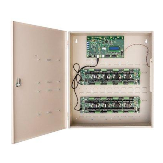
OVERVIEW
General Control
Module
Access Control
Module
Types of Mounting
The iSTAR Ultra consists of the following hardware components:
General Controller Module (GCM)
Access Control Module (ACM) - a maximum of two can be connected
The GCM is a General Purpose Module running the Linux
The GCM provides the following features:
Two network Gigabit Ethernet ports.
Two RS-485 Ports for Aperio™ Hubs and Wireless Readers.
An LCD panel that displays the current status, and provides built-in
diagnostics.
Four USB ports to communicate with the Access Control Modules (ACM)
and import encryption keys.
USB Ports have only evaluated by UL for connection to ACMs.
One Micro A-B port. (For future use)
The ACM is a special purpose Access Control Module that interfaces with the
GCM and provides inputs, outputs, reader interfaces, and AUX outputs (12
Vdc). An iSTAR Ultra can contain up to two ACMs that interface directly with
Wiegand signaling devices, and RM reader busses. The RM reader busses can
interface with Wiegand signaling devices and ABA (magnetic) signaling
devices. External lock power can be sourced directly from the ACM when the
relay(s) are set to "wet", or can be run in "dry" mode with an external power
supply. FAI (Fire Alarm Interface) is also supported along with the ability to
selectively latch the relays until released by a Key switch.
The iSTAR Ultra and its components can be installed in a wall mount enclosure
or in separate rack mount enclosures.
iSTAR Ultra Controller
Hardware Installation
Version A0
Part Number UM-266
April 2014
®
operating system.
1
Advertisement
Table of Contents

Related Manuals for Software House iSTAR Ultra


Summary of Contents for Software House iSTAR Ultra
- Page 1 GCM and provides inputs, outputs, reader interfaces, and AUX outputs (12 Module Vdc). An iSTAR Ultra can contain up to two ACMs that interface directly with Wiegand signaling devices, and RM reader busses. The RM reader busses can interface with Wiegand signaling devices and ABA (magnetic) signaling devices.
-
Page 2: Site Requirements
The iSTAR Ultra must be installed and wired according to local and national regulations. All ACM wiring must be shielded. All Control Units of the iSTAR Ultra must be installed in a restricted access, protected area. Non-limited power supply lines must maintain (1/2 inch (1.3 cm)) spacing ... -
Page 3: Wall Mount Hardware
Requirements Wall Mount Hardware Table 2 lists the hardware recommended for wall mounting the iSTAR Ultra. The hardware listed in Table 2 is not included with the iSTAR Ultra. You must consult a structural expert if you plan to wall mount the iSTAR... -
Page 4: Wall Mount Installation
Installation INSTALLATION This section assumes that the site meets the requirements. The iSTAR Ultra does not include mounting hardware. See Table 2 on page 3 for more detail. ELECTROSTATIC SENSITIVE DEVICES: Observe precautions for handling. Before handling any internal components, discharge static electricity by ... - Page 5 Figure 1 on page 5 for the location of the keyhole slots, screws, and NOTE knockouts. Figure 1. iSTAR Ultra Controller with Door Removed (Two ACMs Mounted) General Controller Keyhole Module (GCM) Mounting Assorted Knockouts...
- Page 6 NEC Codes or the applicable Local codes. Wall Mount Door Components The wall mounted iSTAR Ultra has stand-off’s on the enclosure door that can support up to four RM Bus components. The I/8, I/8-CSI, and R/8 boards are supported.
-
Page 7: Rack Mount Installation
Installation Figure 2. Wiring Wall Mount Door Components Rack Mount Installation The GCM and ACMs are mounted separately in standard 19-inch racks. The cables will be inside the cable management system of the rack. The components must remain secure, be clearly labeled, and be easily accessible when using the correct tools. -
Page 8: Rack Mount Considerations
Installation Rack Mount Considerations Be aware of the following considerations when mounting the iSTAR Ultra as a Rack Mount: Rack Mount ACM's need to located close enough so that the 3 foot USB supplied cable can be routed and still have a proper service loop. - Page 9 Power POWER This section provides the power requirements for the iSTAR Ultra and its components. Electrical Electrical ratings are dependant upon the configuration. Input 12 Vdc , 1.5 - 4.5A max. Output RS485: 11-11.14 Vdc , 1.5A max. each The GCM RS-485 ports have not been evaluated by UL.
- Page 10 The system power circuit breaker must only be assessable by Authorized Personal. FOR BURGLAR ALARM INSTALLATIONS: The iSTAR Ultra is not provided with backup power. An external power supply must be provided with the following characteristics: • UL 603 and UL 294 Listed Minimum four hours of standby power ...
-
Page 11: Wiring Requirements
The Power Input terminals on the iSTAR Ultra accept conductor size up to 2mm AWG). Table 4 on page 11 lists the general wiring requirements for an iSTAR Ultra and its components. Table 4. Equipment Wiring Specifications Signal From... - Page 12 The Tamper, Low Battery, and AC power fail inputs must be enabled and NOTES connected to the iSTAR Ultra to report for compliance with UL requirements. For UL listed products, burglar alarm inputs must be supervised. UL Listed panic hardware shall be used to allow emergency exit from a ...
- Page 13 Readers and Accessory Boards READERS AND The following readers and accessory boards are UL supported: ACCESSORY Wiegand Signaling Readers: BOARDS SWH-4000 SWH-4200 SWH-2100 SWH-4100 SWH-5100 P345MTR P345KPMTR HID 5365 series HID RP40 multiCLASS ...
-
Page 14: Network Connections
It may take several minutes for the formatting and saving of the data.The iSTAR Ultra is fully capable of operating without contact with the Host after the reboot. (Use SW2 to reset the unit to factory default settings.) SW2 - Hard Processor Reset SW2 resets the unit back to the factory default settings. - Page 15 In addition to clearing memory, SW2 can be used to restart the Linux operating system and possibly clear up an error or hang situation. Software House recommends contacting Technical Support before executing a factory reset. SW3 Rotary Switch SW3 is an onboard 16-position rotary switch.
- Page 16 FIPS 140-2 is not evaluated by UL. CPNI - S1-2 When this switch is set to ON, the iSTAR Ultra runs in CPNI (Customer Proprietary Network Information) mode and all database and transactions are stored in RAM. The database and transactions are not backed up on the SD.
- Page 17 General Control Module LCD Contrast Potentiometer - RV1 Used to adjust the contrast of the LCD. Requires a 2 mm screwdriver. USB Ports Four Host Ports (Two Dual Ports) J8 and J9 The ACM communications cables connect to these Ports. It does not matter ...
- Page 18 General Control Module Tamper - J1 Figure 5 on page 18 shows Tamper - J1 NC (Normally Closed). It is connected to the Tamper switch on the enclosure. If there is no standard enclosure, be sure that there is a jumper across the two pins. Figure 5.
-
Page 19: Visual Indicators
Visual Indicators COMM Board Connector - J15 Not supported. VISUAL INDICATORS Power - DS1 and DS2 Indicates that power is supplied to the unit. The LCD display diagnostic messages are similar to the iSTAR Edge and iSTAR eX. As with the iSTAR eX and iSTAR Pro, the LCD is used for status and diagnostics. -
Page 20: Access Control Module
Access Control Module The ACM provides Readers, Inputs and Outputs used in access control. An iSTAR Ultra contains either one or two ACMs. The ACM has eight different sections that contain all of the components needed for a Door as indicated below: RS-485 Port for an RM Bus or other RS-485 Reader. - Page 21 Access Control Module Figure 6. ACM Right Side- Sections 1 and 8 The various user visible controls, connectors and displays are shown. Sections 1 and 8 are indicated on most of the components. The jumper technique for wet or dry relays is shown on the left. The power connector labelled Reader is used for the reader and the logic.
-
Page 22: Switches And Jumpers
Access Control Module Figure 7 on page 22 shows the other end of the ACM and locates the USB client connector, ACM Reset, and some of the LED locations. Sections 4 and 5 are shown here. Figure 7. ACM - Left Side Switches and Jumpers SW10 - ACM MCU Reset SW10 reboots both MCUs. -
Page 23: Jumper Settings
switches. When set to Dry, use the C, NO, and NC connections. When Wet, the iSTAR Ultra sources the power from LOCK Power 1 or lock Power 2. When set to Wet, use the GND, NO, and NC connections. -
Page 24: Ports And Connectors
Access Control Module FAI on this ACM - SW31 There are identical FAI controls on all ACMs. Set this switch to ON on the ACM that is sensing the FAI and KEY signals. Set the switch to OFF on the other ACMs. -
Page 25: Wiegand Connections
Access Control Module LOCK 2 Power - J3 This is one of the power inputs to the relay outputs that are jumpered as Wet LOCK 2. It can be either 12 Vdc or 24 Vdc. It will also supplement the J4 Reader Power. FAI F and Key - J84 The FAI signal is NC and the Key signal is NO. - Page 26 Access Control Module The data line maximum lengths are: 18 AWG - 500 feet 20 AWG - 300 feet 22 AWG - 200 feet Table 7 describes the pinouts. Table 7. Wiegand Port Pinouts Wiegand Port Pin Number Signal/Function Power (+12 Vdc or +5 Vdc) GND - PWR Return...
- Page 27 The AUX outputs can supply 1.5A for motion sensor or PIR type devices. The voltage is 12 Vdc. Figure 12. AUX Wiring Wire the switch contacts of the PIR to one of the iSTAR Ultra inputs, using the proper resistor supervision. INPUTS J13, J40, J42, J17, J44, J72, J68, J69 There are 24 onboard inputs, in sets of three, available on the ACM.The Input...
- Page 28 Access Control Module Pins 2, 4, and 6 of the Input connectors are common Ground. Figure 13. ACM Inputs Supervision Wiring The wiring of supervised inputs is shown in Figure 14. Note that the resistor network is different for Normally Opened (NO) and Normally Closed (NC) switches.
- Page 29 Access Control Module ACM LED Functions Table 10. ACM LED Functions Function Comment DS21 Main Power - Reader Power - J4 12 Vdc DS52 Main Power - LOCK 1 - J2 12 or 24 Vdc DS54 Main Power - LOCK 2 - J3 12 or 24 Vdc Relays DS14...
-
Page 30: Compliance Information
Compliance information Table 11 on page 30 summarizes the RS-485 LEDs for Power, Tx, and Rx. Table 11. ACM RS-485 LED Functions RS-485 Connector LED - Tx LED - Rx DS28 DS27 DS23 DS25 DS22 DS20 J101 DS51 DS50 DS44 DS43 DS41 DS42... - Page 31 Communications du Canada. Access Control / CAUTION: Equipment changes or modifications not expressly approved by Software House, could void the user's authority to operate the equipment, Burglar Alarm / General and could create a hazardous condition. Safety Regulatory standards - CFR 47 FCC Part 15 B, CE, ICES-003, EN55024, ...
-
Page 32: Important Safety Information
Revision: A0 Release Date: April 2014 This manual is proprietary information of Software House. Unauthorized reproduction of any portion of this manual is prohibited. The material in this manual is for information purposes only. It is subject to change without notice.
Need help?
Do you have a question about the iSTAR Ultra and is the answer not in the manual?
Questions and answers