Advertisement
MR14
OPERATION / PROGRAMMING MANUAL
INPUTS / OUTPUTS AND LEDS
LED1, LED2, LED3 e LED4 - memory position indicators to be programmed for channel 1
LEDs
LED5, LED6, LED7 e LED8 - memory position indicators to be programmed for channel 2
LED1 LED2 LED3 LED4 LED5 LED6 LED7 LED8
JOIN
SEL
1 2 3 4 5 6 7 8 9 10 11 12
DIPPER
Basic operation:
Dipper 1 → ON;
Dipper 2 → OFF;
Dipper 3 → OFF.
1
WORKING
ALWAYS
MODE
ON
2
30 SECONDS
7 SECONDS
3
ACTIVED
DEACTIVATED
BUZZER
BUZZER
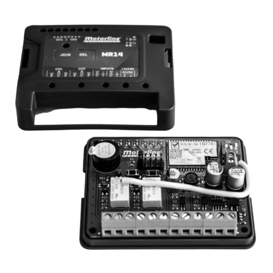
The MR14 receiver is a wireless receiver for managing multiple MX14 emitters.
When receiving information from the emitter, it communicates with the automation
control board via cable, so that the automation can be stopped or reversed.
• Power Supply
• ECO Inputs
• Relay
• Working frequency
• Memory for emitters
• Range in open field
• Dimension
• Protection degree
Relay output NO channel 1
1 •
NC
> the output is active when any channel 1 emitter is in error
2 •
COM
ON
(ex: Door hit an obstacle, communication failed or the battery ran out).
3 •
8k2
The NC or NO output must be connected to the control board.
1 2 3
Relay output NO channel 2
4 •
NC
> the output is active when any channel 2 emitter is in error
5 •
COM
(ex: Door hit an obstacle, communication failed or the battery ran out). The
6 •
8k2
NO or NC output must be connected to the control board.
7 •
CH1
12/24V mode input
8 •
COM
> used to activate channel 1 or 2 in ECO mode (Dipper 1 OFF). The control
9 •
CH2
board must activate this input when the door starts to move.
10 •
COM
11 •
+
12/24Vdc/ac power supply
12 •
-
The Auto test is an external signal that checks the relay
(there is one for each channel).
Dipper 1 allows you to select the desired type of operation.
• OFF – Working mode - Recommended for the optical
sensor
> The working mode allows you to activate/
deactivate the optical sensor. When the optical
sensor is active, a communication test takes place.
Communication is also tested every 7 or 30 seconds.
This mode allows energy saving.
• ON – "Always ON" mode - Recommended with 8k2,
NC, NO or tilt sensor
> The communication is tested every 7 or 30 seconds,
according to the position of dipper 2.
In dipper 2 can set the self check period.
> It makes automatic recognition every 30 seconds or
every 7 seconds.
• OFF – 30 seconds
• ON – 7 seconds
Dipper 3 • Buzzer (beep)
• OFF – Active buzzer
• ON – Deactivated buzzer
EN
TECHNICAL CHARACTERISTICS
AES encryption
Graphic representation of the Auto Test:
WORKING MODE
Power supply
Auto test
Relay output
"ALWAYS ON" MODE
Power supply
Auto test
Relay output
12-32Vdc / 12-24Vac
12/24V
30Vdc 1A/125Vac 0.5A
Self-adjusting 868 MHz
8
50m
81 x 65 x 20 (mm)
IP30
ON
OFF
OFF
ON
ON
OFF
DELAY
DELAY
ON
OFF
ON
ON
OFF
DELAY
DELAY
ON
OFF
ON
OFF
ON
Advertisement
Table of Contents

Related Manuals for Motorline professional MR14


Summary of Contents for Motorline professional MR14
- Page 1 MR14 OPERATION / PROGRAMMING MANUAL The MR14 receiver is a wireless receiver for managing multiple MX14 emitters. When receiving information from the emitter, it communicates with the automation control board via cable, so that the automation can be stopped or reversed.
- Page 2 ON – Programming mode active; OFF – Programming mode inactive. • PIN HEADERS → CHANGE CHANNEL: NOTE • Whenever more than one MR14 is used in the same place, the selected channels must be different from each other. Otherwise interference may occur.
- Page 3 4 • G → 0V output - activated 5 • COM during opening maneuvers 5 • B → 0V output - activated during pause time MR14 CONTROL BOARD LED1 LED2 LED3 LED4 LED5 LED6 LED7 LED8 1 2 3 JOIN...
Need help?
Do you have a question about the MR14 and is the answer not in the manual?
Questions and answers