Table of Contents
Advertisement
Quick Links
Advertisement
Table of Contents

Summary of Contents for BGI PQ100
- Page 1 PQ100 Air Sampler INSTRUCTION MANUAL Firmware Version 5.X and lower REFERENCE SAMPLER DESIGNATION NO. RFPS-1298-124 8 BGI Incorporated 12100 West 6th Ave. Lakewood, CO 80228 Tel: 781.891.9380 Fax: 781.891.8151 e-mail: info@bgiusa.com www.bgiusa.com Manual Version: 6.24 Nov. 2008...
-
Page 2: Preface
• Always operate the PQ100 in a normal, upright position. The legs should be bolted down to prevent tipping in conditions of high winds. • Do not operate the PQ100 if any of the parts are defective, damaged, or missing. -
Page 3: Table Of Contents
User Supplied Items ....................3 HOW TO USE THE PQ100 IMMEDIATELY ...............4 What the Buttons do ....................4 Running the PQ100 at 16.7 Liters per Minute ............4 Downloading (A Quick Start Overview) ..............6 SPECIFICATIONS ......................8 Flow Rate Precision, Accuracy and Pulsation .............8 Run Times for Various Applications ..............8... - Page 4 Running the Pump ....................18 6.8.1 Start Time Disabled .................18 6.8.2 Start Time Enabled ..................18 6.8.3 Run Time ....................18 6.8.4 Acoustic Phenomena at High Negative Pressure........19 Verifying the Flow Rate ..................19 6.10 Resetting the Run ....................19 CALIBRATION .......................20 Entering and Using Calibration Mode ...............20 Using a DeltaCal or TriCal .................21 Using a Rotameter ....................22 Calibration Notes ....................23...
- Page 5 APPENDIX K. FIGURES ......................50 APPENDIX L. FILTER HANDLING, AND WEIGHING .............59 APPENDIX M. EXTERNAL DATALOGGER ...............61 APPENDIX N. SOLAR PANEL POWER SUPPLY ...............66 APPENDIX O. RIGID MOUNTING ASSEMBLY ..............74 APPENDIX P. PQ167 HIGH ALTITUDE (miniPM ) .............78 PQ100 Instruction Manual Revision History ................83...
-
Page 6: Introduction
The PQ100 was designed to operate from 1 standard liter per minute (1000 cc per minute) to 25.0 standard liters per minute and is unaffected by changes in ambient temperature and barometric pressure. - Page 7 SIZE SELECTIVE INLET OR FILTER PULSATION DAMPING MASS FLOW VOLUME PUMP SENSOR MICRO PROCESSOR BATTERY CHARGER A.C. POWER SUPPLY BATTERY VISUAL DATA DISPLAY SCHEMATIC DIAGRAM OF PQ 100 SYSTEM 1910...
-
Page 8: Getting Started Checklist
PQ100 from damage). Note: Permanent damage can occur if the PQ100 is operated without a filter in series with the Inlet. If the unit is operated without a SSI head with filter and holder, a suitable filter must be... -
Page 9: How To Use The Pq100 Immediately
"RESET" Press after a sampling job to clear all the counters in preparation for the next sampling job. "RUN/STOP" Use when the PQ100 has been reset and programmed for another run and you now wish to start the pump. "+"... - Page 10 Press "SETUP" Screen reads; "Select FLOW RATE" To change TARGET FLOW RATE; * Press ENTER (Whole number value will remain on constant while the tenths still blink); use "+" or "-" to increase or decrease until 16 is displayed. * Press ENTER (Tenths value will now remain constant while whole number blinks);...
-
Page 11: Downloading (A Quick Start Overview)
APPENDIX E) force the unit to terminate the sample job. During the initial time that the PQ100 requires to stabilize its flow rate, flow will be displayed as --.-Lpm. If the START TIME ENABLE is set to "ON" then the message "Alarm Triggered Run..."... - Page 12 PQ100. Connect the cable provided from your computer to the UTILITY ADAPTER port on the front of the PQ100. NOTE: THE PQ100 MUST BE AT THE "MAIN IDLE DISPLAY" FOR THE DOWNLOAD TO WORK. When the download is complete you may then select "s" from the "PQ MAIN...
-
Page 13: Specifications
112.0cm H2O 13.0 Hours 12.0 Lpm 37mm MCE .8 94.0cm H2O 13.5 Hours 12.0 Lpm 25mm MCE .8 170.0cm H2O 11.6 Hours 10.0 Lpm 37mm MCE .8 66.0cm H2O 19.8 Hours 2.2 Lpm 37mm w/BGI-4 Cyclone 5.0cm H20 67.0 Hours... -
Page 14: Dimensions And Weights (Pq100 Main Unit Only)
9V Nom. Inputs- 30V Max. Charging System- 120VAC (60 Hz) or 240VAC (50 Hz) Note: The PQ100 can run from the Charger. Hardware Requirements for PQ Software IBM XT, AT or 100% Compatible Clone MS-DOS Operating System version 2.1 or greater Minimum one 3.5, 5.25, Low or High Density Floppy Drive... -
Page 15: Dimensions, Weights And Flow Specifications For Ssi
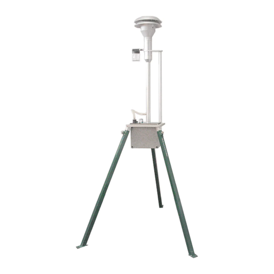
Dimensions, Weights and Flow Specifications for SSI SSI-10 Inlet Kit (Including Rigid Tripod Assembly) Flow Rate: 16.7 Lpm 5% Weight: 16 Lbs. (7.3Kg) Tripod Diameter Footprint: 51" (1.29M) Tripod/Inlet Overall Height: 76" (1.93M) -
Page 16: Accessories
ACCESSORIES Cables Connects the PQ100 to a computer for downloading Communication Adapter Cable Use to connect the PQ100 to a large external battery, External High typically 80 Amp Hour for greater than 48 hour run time Capacity Battery Cable Inlets, Adapters and Filter Holders PQ102 For attachment of a rubber hose to the PQ100. -
Page 17: Batteries And Chargers
Batteries and Chargers PQ101 Battery Charger Used to Recharge system batteries and to power Auxiliary Power Supply the PQ100 for long run times when AC Power is available. PQ103 Replacement Battery Miscellaneous TP100R Supports Dicot Inlet at EPA recommended height... -
Page 18: Operation Details
OPERATION DETAILS Basic Operation To operate the PQ100 Air Sampler, press the Power "On/Off" pushbutton keyswitch. The unit will beep a few times and display; BGI PQ100 Air Sampler and briefly, the unit serial number and firmware revision; SN:1234 Version 5.23 and then;... -
Page 19: What To Do Next
= Liters per minute y = tenths of a Liter per minute The target flow rate is that which the PQ100 will draw air through the inlet at when a run is initiated. If the displayed flow rate is acceptable and you do not wish to change it, press the "Setup"... -
Page 20: Setting The Date And Time
Setting the Date and Time From the "MAIN IDLE DISPLAY" press the "Setup" key twice until the message below appears; Set DATE and TIME dd mmm yyyy hh:mm where; dd = day of the month mmm = month yyyy = year hh = hour (0-24, 24 hour system) mm = minutes (0-59) The date and time are read from the real time clock just prior to entering this screen. -
Page 21: Setting The Start Date And Time
This function can be disabled. This means that if the Enable (eee) is set to "Off", the PQ100 will begin to run the pump immediately when the "Run/Stop" key is pressed from the "MAIN IDLE DISPLAY"... -
Page 22: Setting The Run Time
Setting the Run Time From the "MAIN IDLE DISPLAY" press the "Setup" key four times until the message below appears; Set RUN TIME Hours:hh Min:mm Where; hh = hour (0-99 hours) mm = minutes (0-59) eee = enable "On" or "Off" This sets the length of time that the sampler will run the pump for. -
Page 23: Running The Pump
Flow Rate indicated is a coarse approximation and is somewhere 10% of that displayed. Use the Calibration Mode to set this to 2%. During the initial time that the PQ100 requires to stabilize its flow rate, flow will be displayed as --.-Lpm. -
Page 24: 6.8.4 Acoustic Phenomena At High Negative Pressure
6.8.4 Acoustic Phenomena at High Negative Pressure When running the PQ100 at very high load pressures (i.e. 150 centimeters of water or better), a metal popping sound may be heard by the user. This is merely the internal pulsation dampner (Plenum) adjusting its chamber area. The PQ100 will alert you as to the nature of any problems via the shutdown messages as described in APPENDIX E. -
Page 25: Calibration
IDLE DISPLAY AND PRESS "RUN/STOP". BE CERTAIN THAT THE START DATE ENABLE IS SET TO "OFF" (SECTION 6.9). This mode is used to Calibrate the PQ100 at a target flow rate. It should be noted here that each individual target has it's own independent calibration storage area and is non-volatile. -
Page 26: Using A Deltacal Or Trical
The use of a DeltaCal or TetraCal (formally triCal) is highly recommended for calibration of the PQ100. Connect either unit to the PQ100 just before the filter holder and read the actual flow on the display. More information on the DeltaCal or TetraCal (formally triCal) may be found at www.bgiusa.com/cal/index.htm... -
Page 27: Using A Rotameter
Using a Rotameter Calibrating the PQ100 Air Sampler with a Rotameter is to be avoided for two reasons. The PQ100 is more accurate (.5% of the expected flow rate) than the typical rotameter (within 3% of Full Scale). Secondly, the rotameter, unlike the bubble meter, has a reference condition calibration and requires a correction for ambient conditions. -
Page 28: Calibration Notes
Lpm. That means 9.66 Lpm could actually vary from 9.06 to 10.26 Lpm! Therefore, if a rotameter must be used with the PQ100, the corrections are pointless and a straight 10 Lpm read from the rotameter should be utilized. The accuracy of the PQ100 is now degraded to 5%. -
Page 29: Installation And Use Of The Pc Software
INSTALLATION AND USE OF THE PC SOFTWARE Supported Hardware Any IBM PC or compatible running MS-DOS 2.1 or higher with 1 floppy drive and at least 512K of memory. Any video adapter, Color or Monochrome, may be used. A hard drive is useful but not required. -
Page 30: Running The Program
PQ allows the user to communicate with the PQ100 Air Sampler and downloads Run Data from the PQ100 to your PC. The data may then at a later time be appended with the measured final filter weight, printed and stored for later use. -
Page 31: Beginning A Sample Job
When a sample job has been completed, the data pertaining to the run is stored in the PQ100 until it is reset by the user. Prior to resetting the PQ100 for its next run, the data should be downloaded using the PQ software to provide information such as run time, total sample accumulated, cause of the shutdown etc. -
Page 32: Adding The Final Filter Weight
8.10 Adding the Final Filter Weight Upon completion of the sample job, the final filter weight must be determined and this final weight entered in order to compute concentration. From the PQ Main Menu press "a" to Add the final filter weight. Again you are asked for the appropriate file name and again you must be careful to select the proper file. - Page 33 generating based on a particular site etc. select "n"ew. If you want to add records to build a database, press "a"ppend. This is used to combine a number of run files into a multi record database with each job file as a record. For a more detailed description of the use of this type of file refer to the users manual of your database program.
-
Page 34: Ac Power Supply/Charger
The PQ100 should be Recharged before use to allow for the greatest available Run Time. Connect the Charger to the PQ100 Utility Adapter socket located on the front panel. Plug the Charger into an appropriate power source. BE SURE TO CHECK CHARGER SPECIFICATIONS FOR CORRECT POWER SOURCE INPUT. -
Page 35: Maintenance And Service
MAINTENANCE AND SERVICE 10.1 Replacement Component List The following is a list of components for replacement and/or servicing the PQ100 and may be ordered from the factory (Refer to drawing figures 1 thru 7 for identification by Item#); Item# Fig. - Page 36 Item# Fig. Description ------- ---- ----- --------------------------------- Buna 113 O Rings Clock Battery MFS1 Mass Flow Sensor Hose PQFP Front Panel Assembly SC0104 #6-32 x 3/8" Flat Head Screws BP001 Rubber Bumper BATT.PCA P.C. Ass=y, Battery PQ102 Hose Adapter B1292 Valve Upper Plate B1293 Valve Lower Plate...
-
Page 37: Rebuilding The Pump After 5000 Hours
To determine "Pump Cumulative Time" you must use the PQ software to obtain a download from the PQ100 (See Section 8.9). Pump Cumulative time is the number of actual service hours of the dual diaphragm pump and is shown when either printing or screen viewing a download. -
Page 38: Replacement Of The Mass Flow Sensor
10.3 Replacement of the Mass Flow Sensor As each mass flow sensor is unique and will present variations in operation, all stored calibrations are obsolete when the sensor is replaced. Each flow sensor replacement kit contains an 8 pin DIP Integrated Circuit (I.C.) that must be replaced (socketed) on the main printed circuit board. -
Page 39: Warranty Information
We make no warranty, express or implied, except as set forth herein. BGI's liability under this warranty extends for a period of one (1) year from the date of BGI's shipment. It is expressly limited to repairing or replacing at the factory during this... -
Page 40: Appendix A. Calibration Equations
APPENDIX A. CALIBRATION EQUATIONS Because the PQ100 uses a "Through Stream" mass flow sensor, the mass flow is not affected by pressure and temperature. However, the velocity (flow rate) through a fixed area nozzle will vary with atmospheric conditions. When work is carried out in an area with conditions other than Engineering Standard Conditions the "Corrected Flow Rate"... - Page 41 2.592 10.0 (---------- ) = 9.899 Liters per minute Therefore, if you set a Target Flow of 10.0 Lpm on the PQ100 and 9.90 Lpm on the flow meter, you will always be sampling at 10.0 Lpm to Standard Conditions regardless of changes in the weather (i.e.
- Page 42 Appendix M, 8.2.4 July 18, 1997. When applying these instructions to the PQ100, the following steps are suggested: Place a clean filter of the type to be used for the sampling in the PQ100 filter holder. Remove the PM10 inlet and connect a bubble meter to the filter holder. BGI adaptor (P/N L-30) is convenient for this purpose.
- Page 43 Tstd = 10ΕC, outdoor location, seasonal average Pstd = 720 mm of Hg Target flow rate = 16.67 lpm (desired volumetric flow at above conditions) Tlab = 22ΕC (conditions in calibration location) Plab = 760 mm of Hg Corrected flow rate = 16.95 lpm (flow in calibration location) In the event that a computer is unavailable, the above example may be calculated manually: Plab...
-
Page 44: Appendix B. Troubleshooting
Pressing the "Run/Stop" key causes the unit to shutdown. Answer: This indicates that the PQ100 is now powered off and ready to begin a sample run at the designated Start Date and Time. It means that the enable for the Start Date and Time is set to "On"... -
Page 45: Appendix C. System Batteries
If the battery is allowed to get too low (ignoring the warnings) you may not be able to power off the PQ100 (It will keep waking up after a shutdown). -
Page 46: Appendix D. Military Time Chart
APPENDIX D. MILITARY TIME CHART The following chart is supplied for users who are unfamiliar with a 24 hour Military type time system. 00:00 12:00 Midnight 01:00 1:00 AM 02:00 2:00 AM 03:00 3:00 AM 04:00 4:00 AM 05:00 5:00 AM 06:00 6:00 AM 07:00 7:00 AM 08:00 8:00 AM... -
Page 47: Appendix E. Shutdown Messages
APPENDIX E. SHUTDOWN MESSAGES The following is a description of the various messages that can be displayed by the PQ100 or the PQ Software to indicate the reason for sample job termination or current status of the PQ100; Download not yet Appended! PQ Software * Indicates that a previously created job file has yet to receive a download from a PQ100 Sampler. - Page 48 * Indicates that the sample job was terminated when an operator has pressed the "RUN/STOP" button while a sample job was in progress. RUN TIME EXCEEDED! PQ100 * Indicates that the PQ100 can not initiate a run as the RUN TIME (See Section 6.7) has not been reset. REPLACE CLOCK BATTERY! PQ100...
-
Page 49: Appendix F. Assembling The Pq167 Pm10 Air Sampling System
Item# Qty.. PN Description ------- ----- ---- ----------------------------- PQ100 Air Sampler Main Unit PQ101 Battery Charger (specify 120 VAC or 240 VAC) PQ102 Hose Adapter PC Communication Adapter Cable Manual and Software CD 1 Meter of Rubber Hose... -
Page 50: Appendix G. Assembling The Bgitsp Air Sampling System
Included with your PQTSP Air Sampler System are the following items (Item#'s are indicated on the appended drawings); Item# Qty. Description ------- ----- ---- ---------------------------------- PQ100 Air Sampler Main Unit PQ101 Battery Charger (specify 120 VAC or 240 VAC) PQ102 Hose Adapter PC Communication Adapter Cable Manual and Software CD 4,5,9,10... -
Page 51: Appendix H. Installing Filter Media
APPENDIX H. INSTALLING FILTER MEDIA Referring to Figure 4, the filter media is placed on screen (7) and placed on the inner lip of cassette base (8). Cassette top (6) is then inserted into cassette base when pin of base is aligned with locating hole on cassette top. -
Page 52: Appendix I. Concentration Equation
APPENDIX I. CONCENTRATION EQUATION For reference, the following is the formula for Concentration used by the PQ Software; CONTAMINANT WEIGHT (mg) x 1000 micrograms ------------------------------------------------- = CONCENTRATION ( ------------- ) TOTAL SAMPLE VOLUME (m Where; (CONTAMINANT WEIGHT) is the difference between initial filter weight and final filter weight (TOTAL SAMPLE VOLUME) is the Volume of air passed through the filter in... -
Page 53: Appendix J. Flow Rate Stability
The initial flow rate is measured one minute after the instrument has stabilized the flow rate (The flow rate is stable when the PQ100 visual display shows the actual flow rate instead of "Q--.-"). The flow rate is then sampled once every hour thereafter until the completion of the run with a maximum capability of 30 readings after the initial. - Page 54 In reality all displayed values should be expected to be typically less than 1% and should not exceed 2%. Values more than 2% should be investigated. A blocked or restricted inlet, hose, etc. at precisely the time the PQ100 takes a reading internally should be suspected.
-
Page 55: Appendix K. Figures
APPENDIX K. FIGURES... - Page 56 Figure 1. Exploded Assembly View...
- Page 57 Figure 2. Exploded View of Pump...
- Page 58 Figure 3. Exploded View of Front of PQ100...
- Page 59 Figure 4. Exploded View of Filter Cassette and Filter Holder...
- Page 60 Figure 5. Exploded Assembly with Inlet and tripod (January 2000: OBSOLETE> Parts subject to stock on hand. See Appendix O)
- Page 61 Figure 6. assembled PQ100 Tripod. (January 2000: OBSOLETE> Parts subject to stock on hand. See Appendix O)
- Page 62 Figure 7. Exploded View of PM10 Inlet...
- Page 63 Figure 8. PQ100 Front with Filter Assembly...
-
Page 64: Appendix L. Filter Handling And Weighing
Note: The following guidelines are based on the regulations developed for sampling PM2.5. It is recommended that these guidelines be followed for PM sampling using the PQ100. Filter Specifications For exact compliance with EPA procedures for PM2.5, refer to 40 CFR Part 50, Appendix L, and Section 2.12 of EPA=s Quality Assurance Handbook. - Page 65 BGI. Filter Cassette Handling The filter cassettes provided for use with the PQ100 have been designed with an interference fit to prevent the cassette from coming apart easily, therefore some care must be exercised when opening and closing the cassette, especially when a filter is inside.
-
Page 66: Appendix M. External Datalogger
The BGI Datatrans is a ADownload Data Collector@ designed to extract the AData Download@ from a PQ100 at the end of its sample period and store it until it can be uploaded to a personal computer running BGI PQ software, for more permanent storage. - Page 67 3. Place the connection switch, located on the front panel, in the (Comp) computer position. 4. Insure the computer is running BGI PQ Software for DOS. (B)egin a new job, then import data from the sampler should be selected and should be ready to receive data as if it were attached directly to the sampler.
- Page 68 NOTE: TO RECYCLE SAMPLE RUNS: If after all runs have been downloaded, a lost file, mistake or a problem is discovered and you must download a run again, the Datatrans allows the runs to be recycled as long as it has not yet been erased as described in the Erasure Procedure below.
- Page 69 GREEN YELLOW CONNECT POWER BGI INCORPORATED WALTHAM, MA. 02451 (781) 891-9380 DATATRANS Figure M1. Schematic Diagram of Datatrans...
- Page 70 Figure M2. Datatrans with Adapter for use with PQ100...
-
Page 71: Appendix N. Solar Panel Power Supply
APPENDIX N. SOLAR PANEL POWER SUPPLY Introduction The SP32, solar panel kit is intended to permit the PQ100 to run for extended or, indefinite periods of time depending on the available sunlight (solar radiation) at a given location. The solar panel may only be used as the sole source of power for a U.S. EPA-designated instrument if sampling is not being performed every day (i.e., continuously). - Page 72 45Ε latitude. Setting up Subsequent to unpacking a new unit, it is attached to the rear leg of the PQ100 as shown in Figure N1. It is important that the board provided be located as shown in the figure with the battery placed on top of it.
- Page 73 Overall Operation and Troubleshooting Prior to deploying a PQ100 with solar panel, it is prudent to ensure that the internal battery is fully charged. This is accomplished by plugging the PQ100=s power supply into a source of line current for 16 hours.
- Page 74 41Ε 40' Raleigh-Durham, NC Apr-Aug Jan-Dec Jan-Dec Jan-Dec 35Ε 52' Miami, FL Feb-Sep Jan-Dec Jan-Dec Jan-Dec 25Ε 48' NOTE: This approximation is based upon 5 Kwh/M received, as being necessary to fully restore the PQ100 system whilst drawing 500 MA (typical).
- Page 77 VERTICAL MEASUREMENT PQ 100 BEFORE USING THE CHART BELOW DETERMINE WHETHER YOU HAVE THE LONG STYLE (13" WIDE x 51" LONG) OR THE SHORT STYLE (21" WIDE x 25" LONG) SOLAR PANEL VERTICAL MEASUREMENT TILT ANGLE LONG STYLE (13"x51") SHORT STYLE (21"x25") INCHES DEGREES INCHES...
-
Page 79: Appendix O. Rigid Mounting Assembly
PQ100 pump module can be placed, this supports the PQ100 at waist height for ease of use. Three stub legs are welded to the bottom of the support plate, which permits the attachment of 3 legs, which are interchangeable... - Page 80 Included with your PQ167R PM10 Air Sampler System are the following items. Item #=s are indicated on the appended drawings. Item # Quantity Part Number Description PQ100 Air Sampler Main Unit PQ101 Battery Charger/Auxiliary Power Supply PQ102 Hose Adapter Charger/External Battery Cable...
- Page 81 2000 Figure 0.1 PQ167R Rigid Mounting Stand...
- Page 82 Figure 0.2 Exploded View of PQ167R Stand...
-
Page 83: Appendix P. Pq167 High Altitude (Minipm )
APPENDIX P. PQ167 High Altitude (miniPM Inlet) IMPORTANT: FLOW RATE MUST BE SET FOR 5 lpm 1.0 Size selective inlet The size selective inlet will be familiar to all who have had experience with the Standard EPA Louvered Inlet in its original 16.7 lpm configuration. - Page 84 Summary of Maintenance Items: Frequency* Maintenance item Every 5 sampling days 1. Service water collector bottle Monthly 1. Clean inlet surfaces 2. Check inlet screen for any clogging Quarterly (every 3 months) 1. Inspect O-rings. Remove and lightly coat them with Vacuum grease.
- Page 85 Fig. 9 Exploded Diagram of Inlet with Filter Holder...
- Page 86 Figure 10: Photo of Initial Disassembly of Inlet...
- Page 87 The jet may also be removed from the top of the inlet as shown in Figure 11. Figure 11: Photo of Jet Removed for Cleaning or Size Change...
-
Page 88: Pq100 Instruction Manual Revision History
PQ100 Instruction Manual Revision History Version 5.0 Updated to WP6.0 format March 1998 Version 6.0 Added Preface, Safety, Appendix L, M, N, and O December 1998 Added Designation Information Version 6.01 Corrections to Replacement Component List February 1999 Version 6.02 Corrections to Appendix M April 1999 Version 6.03 Corrections to Appendix N...
Need help?
Do you have a question about the PQ100 and is the answer not in the manual?
Questions and answers