
Related Manuals for Helm PTM LOADGARD Series

Summary of Contents for Helm PTM LOADGARD Series
- Page 1 PTM - LOADGARD Series USER MANUAL Revision 6.5 Jan 24, 2019 HELM INSTRUMENT CO., INC.
- Page 2 Helm serviceman, or where the serial number has been defaced or altered. This warranty shall extend for the one (1) year period from date of shipment from our...
- Page 3 Operators Manual PTM LOADGARD Series EXPLANATION OF SYMBOLS Alternating Current Earth (ground) TERMINAL On (Supply) Off (Supply) Caution, risk of electric shock Caution (refer to accompanying documents)
-
Page 4: Table Of Contents
EXPLANATION OF SYMBOLS ..........................ii Introduction................................. 5 ABOUT PTM LOADGARD SERIES ........................... 5 Benefit ..................................5 PTM (Peak Tonnage Module) ............................ 5 Main Features ................................6 OPERATING MODES ........................... 6 LOOK WINDOW TIME (ms) - Only applicable to none Resolver Model ............. 6 SAMPLING (also referred to as “Learning”... - Page 5 Operators Manual PTM LOADGARD Series ALARM WINDOW (Degreee or ms) ......................21 (LOOK) WINDOW TIME (ms) - Only applicable to some of none Resolver Model ........22 ENABLING EDIT ............................22 DOWNLOAD ............................... 22 JOB RECIPE ............................... 23 SAVING TO RECIPE DATABASE ......................23 MAIN MENU ..............................
- Page 6 Operators Manual PTM LOADGARD Series PASTE................................. 36 CANCEL ..............................36 SAVE ................................36 PASSWORD CHANGE ............................37 MASTER PASSWORD ..........................37 ADMINISTRATOR PASSWORD ........................ 37 OPERATOR PASSWORD .......................... 37 INITIAL PASSWORD ..........................37 ADTSERVER SETUP SCREEN ..........................38 Monitor Screen ................................. 38 OPERATING STATUS INDICATOR ......................
- Page 7 Operators Manual PTM LOADGARD Series APPENDIX H ( PTM-4500TSM-ASA )- 4Ch Frame + Auto Shutheight Adjust w/ Resolver Input ......60 APPENDIX I ( PTM-5600P) - 5Ch Piezo Sensor Input ..................61 APPENDIX J ( PTM-4500) - 4Ch Frame with CAM input ..................62 APPENDIX K ( PTM-4500-ADC) - 4Ch Frame with Automatic Die Change Option ..........
-
Page 8: Introduction
ABOUT PTM LOADGARD SERIES PTM LOADGARD series is one of the most advanced load monitoring systems Helm can offer. Sophisticated features such as smart sampling, adaptive learning, SPC(Statistical Process Control) Charts, etc. help monitoring the operation of your machine and protect them from faulty operation. -
Page 9: Main Features
PTM LOADGARD Series EATURES OPERATING MODES PTM LOADGARD Series has three function modes controlled by an operator. • Setup Mode – Used for system setup, Job setup or new job download. Capacity alarms are active. Trend Alarms are active if the Trend Alarm in Setup option is enabled from Server Setup screen. -
Page 10: Other Features
Operators Manual PTM LOADGARD Series • High/Low Tacking – creates high and low tolerance bands around the sample tonnage signature for monitoring the alarm condition through out the stroke. Tracking alarm is only available in Monitor mode Press Curve (only available for Resolver based model) – Since a press may have •... -
Page 11: Touch Screen Interface
Operators Manual PTM LOADGARD Series TOUCH SCREEN INTERFACE MAIN MENU Main menu allows you to access different area of the system. The PTM LOADGARD™ features a touch screen display for easy navigation and operation of the system. Click or touch on the button you wish to access. -
Page 12: Press Monitor
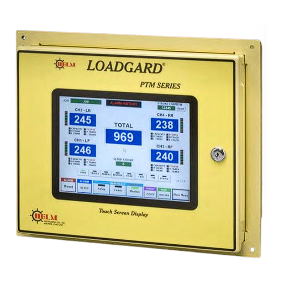
Operators Manual PTM LOADGARD Series PRESS MONITOR ONNAGE ISPLAY CREEN PRESS MONITOR provides the screens to view peak tonnage load, Tonnage signatures, ,peak tonnage history, and SPC charts, You can change Alarm settings and view Alarm Messages as well. MAIN PEAK LOAD SCREEN FOR VARIATY PTM MODELS This screen displays peak tonnage values, alarm settings, and alarm indicators for all channels. - Page 13 Operators Manual PTM LOADGARD Series Main Tonnage screen from PTM-4500L2 Main Tonnage screen from PTM-6100A-SS Main Tonnage screen from PTM-2300PG Main Tonnage screen from PTM-5600P...
- Page 14 Operators Manual PTM LOADGARD Series FOR DOUBLE ACTION PRESS MACHINES Main Tonnage screen from PTM-6600TSM-DA Main Tonnage screen from PTM-8800TSM-DA...
-
Page 15: Current Job Display
Operators Manual PTM LOADGARD Series CURRENT JOB DISPLAY Shows current Job name. Job name can be edited from RECIPE MANAGER screen ALARM INDICATOR & HISTORY This ALARM INDICATOR button has two functions, It indicates any alarms tonnage condition and lets you view alarm history. -
Page 16: Trend Led
Operators Manual PTM LOADGARD Series TREND LED The vertical bar meter next to the peak display box is a Trend Display bar. It shows the visual reference of a peak tonnage variation comparing to TARGET or SAMPLE tonnage for Trend Alarm. The center green light indicates 0% variance within the tolerance of the Trend Alarm. -
Page 17: Viewing Current Alarm Settings (In-Die Screen Only)
Operators Manual PTM LOADGARD Series VIEWING CURRENT ALARM SETTINGS (In-Die Screen Only) Click on one of the buttons to view current alarm setting values. The values will be displayed in the Peak tonnage display boxes for 20 seconds and change back to PEAK automatically. -
Page 18: Copying Sample To Target
Operators Manual PTM LOADGARD Series of sample in Setup mode if enabled. You can enable or disable the Target Trend Alarm in Setup mode from the ADT Server System Setup screen. Learn Mode – In LEARN mode, system averages the peak values for each channel during the predefined learning cycle. -
Page 19: Peak History & Spc(Statistical Process Control) Charts
Operators Manual PTM LOADGARD Series & SPC(S ISTORY TATISTICAL ROCESS ONTROL HARTS The Peak history records up to 40,000 previous peak values and archives up to last 50 data files, totaling stores last 2,000,000 stokes of peak data. Zoom Mode... -
Page 20: Change Graph Resolution
Operators Manual PTM LOADGARD Series CHANGE GRAPH RESOLUTION You can change the number of viewable peak points on a graph by choosing one of the options 100pt – to display 100 peak points at a time 500pt – to display 500 peak points at a time 1000pt –... -
Page 21: Current Alarm Setting
Operators Manual PTM LOADGARD Series URRENT LARM ETTING Resolver TSM model: PTM 2300TSM/4500TSM/6600DA/6700TSM None Resolver model: PTM-4500 In CURRENT ALARM SETTING, you can view / edit the current alarm settings and also save the change to current job database and download the change to ADTServer. -
Page 22: Group Select
Operators Manual PTM LOADGARD Series Group Select Select Group Select option if you want all channels to have same settings. HIGH CAPACITY HIGH CAPACITY is the limit for the maximum peak tonnage allowed to operate the machine. Normally the value is set at or below the scale value which is the capacity of the machine divided by the number of frame sensor channels. -
Page 23: Delta Track Ex (No Longer Applicable)
Operators Manual PTM LOADGARD Series Tolerance settings. However, if the Tracking alarm is enabled, the expand factor still applies to the Tolerance setting for Trend alarm tolerance limits, but not for Tracking alarm band. Example: Target = 60 , Sample = 64, +Tol = 10, -Tol =15, Exp Factor = 2.0 In Setup or Learn mode Actual High Trend limit = 60 + (10 * 2.0) = 80... -
Page 24: Adaptive Learning Enable/Disable
Operators Manual PTM LOADGARD Series ALARM WINDOW(S) Set alarm windows to adjust the area of the force signature to monitor for High/Low tracking alarm. You can set up to 2 separate Tracking Alarm window area. Enter start and stop Alarm Window in degree for TSM model or time(msec) for CAM model within Look Window. -
Page 25: (Look) Window Time (Ms) - Only Applicable To Some Of None Resolver Model
Operators Manual PTM LOADGARD Series (LOOK) WINDOW TIME (msec) - Only applicable to some of none Resolver Model. Look Window Time is the duration of time when the force signature and peak tonnage is captured. The WINDOW TIME need to be adjusted based on the speed of the machine to capture optimal force signature. -
Page 26: Job Recipe
Operators Manual PTM LOADGARD Series JOB RECIPE Click this button to go to RECIPE MANAGER screen. SAVING TO RECIPE DATABASE Click this button to update current job stored in Recipe database with the new settings made from this screen. MAIN MENU... -
Page 27: Press Curve Alarm
Operators Manual PTM LOADGARD Series RESS URVE LARM ETUP The resolver based PTM Loadgard system allows the operator to enter the specified 36 press curve points in the Press Curve Data Setup screen for Press Curve Alarm. Multiple press curve data can be saved. Select a press curve data file and click download to active it. - Page 28 Operators Manual PTM LOADGARD Series B. How to Create a new Press Curve data file. 1. First you need 36 data points from Angle vs. Tonnage capacity graph. 2. Turn Edit On. 3. Click Create button and name your data file using the pop-up keyboard.
-
Page 29: Job
Operators Manual PTM LOADGARD Series Signature (Wave) Display Screen The Signature Display screen displays real-time force signatures for individual channels. The overlaying with other signatures or graphs help you to monitor the operating status of the machine or verify the alarm conditions easier. -
Page 30: Wave Viewing Window
Operators Manual PTM LOADGARD Series WAVE VIEWING WINDOW LEGEND Capacity Alarm Limit Trend Alarm Limit for Peak Tonnage Press Curve Alarm limit P.T. Tracking Alarm Limit ZOOM INDICATOR: This message indicates that the graph is currently zoomed. HIGH CAPACITY: High Capacity limit... -
Page 31: Read Tonnage At Angle
Operators Manual PTM LOADGARD Series READ TONNAGE AT ANGLE Click on this button to enable the Read Tonnage at Angle feature. To view the tonnage angle, click coordination you want to read from the signature screen. You can view up to... -
Page 32: Zoom In
Operators Manual PTM LOADGARD Series ZOOM IN The Zoom feature allows the user to “zoom in” on a selected area of the signature for analysis at a higher resolution. Click this button to put the signature screen in zoom mode. -
Page 33: Grid
Operators Manual PTM LOADGARD Series GRID Click this button to show or hide vertical and horizontal grid lines on the wave screen. BOLD Click this toggle button to make the current signature graph line bold. LEGEND Click this button to show or hide the legend of the graphs displayed on the screen. -
Page 34: Signature Overlay Screen
Operators Manual PTM LOADGARD Series SIGNATURE OVERLAY SCREEN PEAK BARS SCREEN Trend alarm Color coded Alarm Tolerance range Indication High Capacity limit Peak Tonnage reading Peak Tonnage Bar... -
Page 35: Recipe Manager
Operators Manual PTM LOADGARD Series RECIPE MANAGER ECIPE CREEN Recipe Manager is where you can create and store new jobs, edit or delete existing jobs, and download the job you want to set the system for. You can store virtually unlimited number of jobs. -
Page 36: Remove
Operators Manual PTM LOADGARD Series REMOVE REMOVE button deletes a current active job from the Job Summary Display. Select the job you wish to delete and click on REMOVE button. EDIT EDIT button will lead you to JOB SETUP screen where you can make changes of current active job settings such as Job name, alarm settings, etc. -
Page 37: Job Setup Screen
Operators Manual PTM LOADGARD Series ETUP CREEN This is where you can edit or enter new settings for the job you created. JOB NAME Enter a job name for the job you created. This will identify each job in the Job database. You can enter any character up to 20 characters. -
Page 38: Tol
Operators Manual PTM LOADGARD Series disable the Trend Alarm on a channel by channel basis. After system learns the new sample values, you can use the Target Copy command to update the Target values. Note: While the system is in Setup or Learn mode, adjust Expand Factor to increase the tolerance band to avoid unnecessary Trend alarm warning. -
Page 39: Alarm Window (Ms)
Operators Manual PTM LOADGARD Series ALARM WINDOW (ms) Set alarm window to adjust the area of the force signature to monitor for tracking alarm. If PEAK WINDOW is enabled, this ALARM WINDOW determined the area of the signature to capture the peak tonnage instead of from entire signature. Enter start and stop Alarm Window times in msec within Window Time. -
Page 40: Password Change
RECIPE MANAGER screen. Click OPERATOR button to change the Operator password. This requires Operator or higher level of password. INITIAL PASSWORD Master: 1968 Administrator: 123456 Operator: Note: If you forget your passwords, contact HELM INSTRUMENT CO., Inc. at (419) 893-4356... -
Page 41: Adtserver Setup Screen
Operators Manual PTM LOADGARD Series ADTSERVER SETUP SCREEN ADTServer is the core of the engine for the software of this system. ADTServer receives tonnage signal from SCM module, processes the data, monitors the alarm conditions, and handles I/Os. When the system is installed in a machine for the first time, ADTSERVER requires several initial setups from SYSTEM SETUP screen. -
Page 42: Sensor Calibration Screen
Operators Manual PTM LOADGARD Series ENSOR ALIBRATION CREEN Click Calibration button to view a Sensor Calibration screen. Note: To make any changes of the settings, Master level of password is required to turn on the Edit Enable Mode. FRAME SEMSOR... -
Page 43: System Setup Screen
Operators Manual PTM LOADGARD Series YSTEM ETUP CREEN The SETUP screen is where you can configure the initial settings for the system. To make any changes of the settings, Master level of password is required to turn on the Edit Enable Mode. -
Page 44: System Setup Screen For Ptm-5600P/6700P
Operators Manual PTM LOADGARD Series System Setup Screen for PTM-5600P/6700P SCALE SET Default Scale values for Piezo series are set to 267. We recommend using this value as your scale set. This will scale the peak load output value to match with the sensor voltage output. For example, if Ch1 peak shows 157, it means the sensor peak output from PTM Piezo module is 1.57V. -
Page 45: System Setup Screen For Ptm-4500Tsm/6700Tsm/6700I-Tsm
Operators Manual PTM LOADGARD Series PTM-4500TSM/6700TSM/6700 -TSM YSTEM ETUP CREEN FOR LOOK WINDOWS Look Window is the area of the slide position where the force signature and peak tonnage is captured. The LOOK WINDOW needs to be adjusted to capture optimal force signature of the machine. -
Page 46: Ptm Loadgard Adc Setup For Tsm Model
Operators Manual PTM LOADGARD Series PTM LOADGARD ADC SETUP FOR TSM MODEL • Go To ADC Manager From Main Menu screen, if you do not see ADC MANAGER menu button, then click on the hidden button located at the left bottom area of the screen to go to SYSTEM SETUP MENU. - Page 47 Operators Manual PTM LOADGARD Series b. Click SETUP button to go to ADC Setup screen. c. In ADC Setup screen, select a SEQ number to 1, select a COMPORT number where the ADC communication cable is plugged in, and select ASCII PLC ADC MODE option.
-
Page 48: Adc Rs232 Cable Connection
Operators Manual PTM LOADGARD Series • ADC RS232 CABLE CONNECTION 232 connection is possible with PLC as long as the able length is less than Direct RS- 50feet. RS-232 Cable connection... -
Page 49: Getting Ready For Calibration
Operators Manual PTM LOADGARD Series GETTING READY FOR CALIBRATION Make sure proper Look window timing Input is connected to CAM Input of PTM Loadgard. Please refer to the drawing from the Appendix in the manual for connection details. For TSM model, Make sure the Resolver is connected properly instead of CAM input 2. - Page 50 Operators Manual PTM LOADGARD Series 3. Entering Scale values for each Channel. Next thing before the calibration, you need to enter proper scale value for each channel. Scale value is the tonnage that each sensor will measure at full capacity of the machine. For example, if a machine is rated at 800ton as maximum capacity and has total 4 sensors mounted on columns of the machine, then the scale value would be 200 ( 800 / 4 = 200) per channel.
- Page 51 Operators Manual PTM LOADGARD Series 5. Calibrating PTM Modules Move the 3 position switch of the PTM module to Off position 2. Adjust ‘Balance’ potentiometer to show ‘0’ on the Calibration screen for each module. 3. Move 3 position switch of the PTM module to CAL position 4.
-
Page 52: System Specifications
Operators Manual PTM LOADGARD Series SYSTEM SPECIFICATIONS 1. 90-240 VAC input power source @ 3.125 Amp. 2. Automatic Zero Balance (Auto-Zero) 3. 2/4/6 channel load-strain gauge input utilizes 175 - 700 ohm nominal bridge resistance. 4. *24VDC-Cam/Prox/PLC input 5. Hi/Lo Gain Range (1 meg/140K) 6. -
Page 53: Bypass &Remote Alarm Reset
Operators Manual PTM LOADGARD Series BYPASS &REMOTE ALARM RESET OPTION FOR PTM-4500TSM MODEL PTM-4500TSM model has Remote Alarm reset and Bypass option to bypass Low Trend and Low Tracking alarm feature while running. This feature is useful for initial setup procedure after job change while the parts are being fed through a press line. - Page 54 Operators Manual PTM LOADGARD Series ADC ASCII PROTOCOL This protocol is to communication with the ADC port of the PTM LOADGARD directly with optional RS422 serial interface for ADC feature. • Communication Port Setting BAUD rate: 9600 PARITY: None Data Bits: Stop Bits: •...
- Page 55 Operators Manual PTM LOADGARD Series Example) To change the mode to Setup mode for SCM module which is set as Seq#1, 1. Send 9 bye of data below 97, 0, 6,218, 192, 76, 203, 65, 251 2. Wait for response data (9byte) from SCM Autograph 3.
-
Page 56: Appendix A ( Ptm-4500L2 ) - 4Ch Frame With 2 Linear Transducer
Operators Manual PTM LOADGARD Series APPENDIX A ( PTM-4500L2 ) - 4C RAME WITH INEAR RANSDUCER... -
Page 57: Appendix B ( Ptm-2300L ) - 2Ch Frame/Indie With 1 Linear Transducer Input
Operators Manual PTM LOADGARD Series APPENDIX B ( PTM-2300L ) – 2C RAME NDIE WITH INEAR RANSDUCER NPUT... -
Page 58: Appendix C ( Ptm-6700I ) - 6Ch In-Die Applcation
Operators Manual PTM LOADGARD Series APPENDIX C ( PTM-6700 ) – 6C PPLCATION... -
Page 59: Appendix D ( Ptm-5600F ) - 3Ch In-Die + 2Ch Frame Application
Operators Manual PTM LOADGARD Series APPENDIX D ( PTM-5600F ) – 3C + 2C RAME APPLICATION... -
Page 60: Appendix E ( Ptm-6700Tsm ) 4Ch Frame + 2Ch Indea With Resolver Input
Operators Manual PTM LOADGARD Series APPENDIX E ( PTM-6700TSM ) 4C + 2C RAME NDEA WITH ESOLVER NPUT... -
Page 61: Appendix F ( Ptm-4400I ) 4Ch In-Die Application
Operators Manual PTM LOADGARD Series APPENDIX F ( PTM-4400 ) 4C DIE APPLICATION... -
Page 62: Appendix G ( Ptm-4500Tsm )- 4Ch Frame With Resolver Input
Operators Manual PTM LOADGARD Series APPENDIX G ( PTM-4500TSM )- 4C RAME WITH ESOLVER NPUT... -
Page 63: Appendix H ( Ptm-4500Tsm-Asa )- 4Ch Frame + Auto Shutheight Adjust W/ Resolver Input
Operators Manual PTM LOADGARD Series APPENDIX H ( PTM-4500TSM-ASA )- 4C RAME HUTHEIGHT DJUST W ESOLVER NPUT... -
Page 64: Appendix I ( Ptm-5600P) - 5Ch Piezo Sensor Input
Operators Manual PTM LOADGARD Series APPENDIX I ( PTM-5600P) - 5C IEZO ENSOR NPUT... -
Page 65: Appendix J ( Ptm-4500) - 4Ch Frame With Cam Input
Operators Manual PTM LOADGARD Series APPENDIX J ( PTM-4500) - 4C RAME WITH INPUT... -
Page 66: Appendix K ( Ptm-4500-Adc) - 4Ch Frame With Automatic Die Change Option
Operators Manual PTM LOADGARD Series APPENDIX K ( PTM-4500-ADC) - 4C RAME WITH UTOMATIC HANGE PTION... -
Page 67: Appendix Lline Supervisor With Rlg Conenction
Operators Manual PTM LOADGARD Series APPENDIX L LINE SUPERVISOR WITH RLG CONENCTION... -
Page 68: Appendix M ( Ptm-6100-Ss) - 4Ch Frame, 1Ch In-Die, 1Ch Laser Sensor
Operators Manual PTM LOADGARD Series APPENDIX M ( PTM-6100-SS) - 4C , 1C , 1C RAME ASER ENSOR... -
Page 69: Appendix N ( Ptm-6700I-Tsm) - 6Ch In-Die With Trend Warning Output
Operators Manual PTM LOADGARD Series APPENDIX N ( PTM-6700 -TSM) - 6C REND ARNING UTPUT... -
Page 70: Appendix O Ptm Loadgard Dimemsion (Standard Mount)
Operators Manual PTM LOADGARD Series APPENDIX O PTM LOADGARD DIMEMSION (S TANDARD OUNT... -
Page 71: Appendix P Ptm Loadgard Dimemsion (Flange Mount)
Operators Manual PTM LOADGARD Series APPENDIX P PTM LOADGARD DIMEMSION (FLANGE MOUNT) -
Page 72: Appendix P-1 Ptm Loadgard Panel Pc Connections Layout
Operators Manual PTM LOADGARD Series APPENDIX P-1 PTM LOADGARD PANEL PC CONNECTIONS LAYOUT... -
Page 73: Appendix Q (Ptm-884Tsm-Ss) 4Ch Frame, 4Ch In-Die Sensors
Operators Manual PTM LOADGARD Series APPENDIX Q (PTM-884TSM-SS) 4C , 4C RAME ENSORS... -
Page 74: Appendix R (Ptm-844Tsm-Ss) Connection Drawing
Operators Manual PTM LOADGARD Series APPENDIX R (PTM-844TSM-SS) C ONNECTION RAWING... -
Page 75: Appendix S (Ptm-1248Tsm-Ss) 4Ch Frame, 8Ch In-Die Sensors
Operators Manual PTM LOADGARD Series APPENDIX S (PTM-1248TSM-SS) 4C , 8C RAME ENSORS... -
Page 76: Appendix T (Ptm-1248Tsm-Ss) Connection Drawing
Operators Manual PTM LOADGARD Series APPENDIX T (PTM-1248TSM-SS) C ONNECTION RAWING... -
Page 77: Appendix U Rlg Line Supervisor Connection
Operators Manual PTM LOADGARD Series APPENDIX U RLG L UPERVISOR ONNECTION... -
Page 78: Appendix V Ptm-102L Connections
Operators Manual PTM LOADGARD Series APPENDIX V PTM-102L C ONNECTIONS... -
Page 79: Appendix W Ptm-4500Tsm New I/O Board Connections
Operators Manual PTM LOADGARD Series APPENDIX W PTM-4500TSM N I/O B OARD ONNECTIONS... -
Page 80: Appendix X Ptm-6600Tsm For Doule Action Connections
Operators Manual PTM LOADGARD Series APPENDIX X PTM-6600TSM OULE CTION ONNECTIONS... -
Page 81: Appendix Y Ptm-8800Tsm For Doule Action Connections
Operators Manual PTM LOADGARD Series APPENDIX Y PTM-8800TSM OULE CTION ONNECTIONS... -
Page 82: Appendix Z Ptm-2300D-Tsm With Diverter Output
Operators Manual PTM LOADGARD Series APPENDIX Z PTM-2300D-TSM WITH IVERTER UTPUT... -
Page 83: Appendix A1 Profinet Add-On Kit Connection
Operators Manual PTM LOADGARD Series APPENDIX A1 PR OFINET ONNECTION... - Page 84 Operators Manual PTM LOADGARD Series...
-
Page 85: Appendix B1 Ptm-2300-Tsm-Rd (Remote Display)
Operators Manual PTM LOADGARD Series APPENDIX B1 PTM-2300-TSM-RD (R EMOTE ISPLAY... -
Page 86: Appendix C1 Ptm-2100-Ss Laser Sensor Input With Cutter Control
Operators Manual PTM LOADGARD Series APPENDIX C1 PTM-2100-SS L ASER ENSOR NPUT WITH UTTER ONTROL...
Need help?
Do you have a question about the PTM LOADGARD Series and is the answer not in the manual?
Questions and answers
touch screen not switching on
The Helm PTM LOADGARD Series touch screen may not be switching on due to several possible reasons:
1. Power Supply Issue – Ensure the device is properly connected to a power source and that the power switch is turned on.
2. Electrical Connection Problem – Check for loose or disconnected cables.
3. Fuse or Circuit Protection – A blown fuse or tripped circuit breaker may prevent the screen from receiving power.
4. System Setup Issue – If the system settings require a master-level password to enable editing, the screen may not respond until the correct settings are applied.
5. Hardware Failure – A malfunctioning display or internal component may prevent the screen from turning on.
To troubleshoot, check power connections, verify the power source, and inspect for any physical damage or blown fuses.
This answer is automatically generated
@Mr. Anderson when you switch the power on, the screen blink white only once and it turns off.