Advertisement
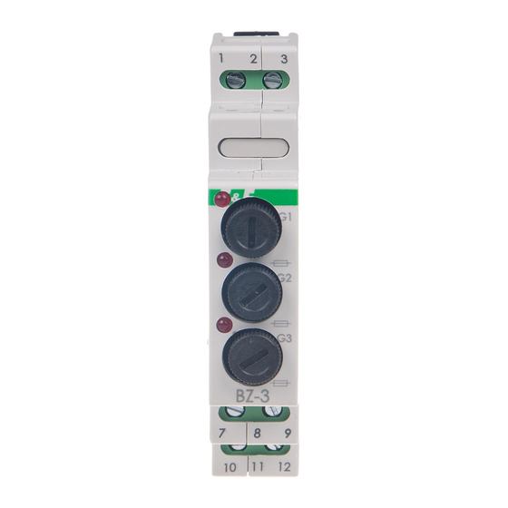
Fuse module,
Do not dispose of this device in the trash along with other waste!
According to the Law on Waste, electro coming from households free of charge and can
give any amount to up to that end point of collec� on, as well as to store the occasion of
the purchase of new equipment (in accordance with the principle of old-for-new, regard-
less of brand). Electro thrown in the trash or abandoned in nature, pose a threat to the
environment and human health.
Purpose
The BZ-3 fuse module is designed to protect electrical receivers from
the effects of a current rise above the permissible value.
Functioning
Activation of the fuse (fuse link blown) is signaled by the illumination
of the red LED.
Absence or failure of the fuse doesn't ensure physical di-
sconnection of the circuit!
Signal diode current (maximum 3 mA) can still flow through
the fuse circuit, which, in the case of protecting low-power
loads (<10 W), may cause the presence of voltage at the out-
put terminals of the fuse and the activation of signal lights
connected to the output of the fuse.
F&F Filipowski sp. j.
Konstantynowska 79/81, 95-200 Pabianice, POLAND
phone/fax (+48 42) 215 23 83 / (+48 42) 227 09 71
www.fif.com.pl; e-mail: biuro@fif.com.pl
BZ-3
3-slots
- 1 -
Advertisement
Table of Contents

Subscribe to Our Youtube Channel
Summary of Contents for F&F BZ-3
- Page 1 Electro thrown in the trash or abandoned in nature, pose a threat to the environment and human health. Purpose The BZ-3 fuse module is designed to protect electrical receivers from the effects of a current rise above the permissible value. Functioning Activation of the fuse (fuse link blown) is signaled by the illumination of the red LED.
- Page 2 Mounting 1. Disconnect the power supply. 2. Mount the module on the rail in the distribution box. 3. Connect the circuit according to the diagram. 4. Install fuse links of the desired value in the holder(s). Fuse-link replacement - 2 -...
- Page 3 Wiring diagram fuse track in socket G1 fuse track in socket G3 10-12 fuse track in socket G2 Internal diagram of a single security track - 3 -...
- Page 4 When protecting DC circuits, the polarity of connection is important. In case of improper connection, the blown fuse indication will not work. Technical data protection ø5×20 mm fuse-link voltage (depending on the fuse-link used) max 250 V AC/DC current max 6.3 A terminal wire 2.5 mm²...

Need help?
Do you have a question about the BZ-3 and is the answer not in the manual?
Questions and answers