Table of Contents
Advertisement
Quick Links
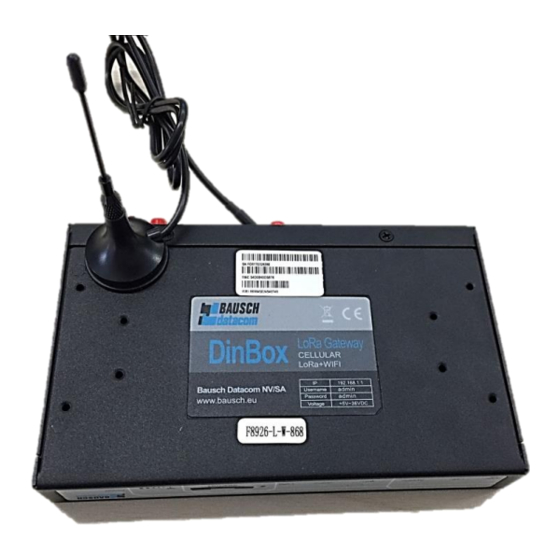
DINBOX LORA
GATEWAY
User Manual
DINBOX LORA GATEWAY Series
The user manual is suitable for the following model:
GATEWAY-G
GATEWAY-
GATEWAY-V
GATEWAY-T
GATEWAY-F
GATEWAY-L
Document Version
Product Name:DINBOX LORA GATEWAY
User Manual
Model
DINBOX
LORA
LoRa+GPRS WIFI Router
DINBOX
LoRa+WCDMA WIFI Router
LORA
W
DINBOX
LORA
LoRa+EVDO WIFI Router
DINBOX
LoRa+TDD LTE WIFI Router
LORA
L
DINBOX
LoRa+FDD LTE WIFI Router
LORA
L
DINBOX
LoRa+LTE WIFI Router
LORA
V2.0.0
Product Type
Page
Total:87
Advertisement
Table of Contents

Subscribe to Our Youtube Channel
Summary of Contents for Bausch Datacom DINBOX LORA GATEWAY Series
- Page 1 Document Version Page DINBOX LORA GATEWAY V2.0.0 User Manual Product Name:DINBOX LORA GATEWAY Total:87 DINBOX LORA GATEWAY Series User Manual The user manual is suitable for the following model: Model Product Type DINBOX LORA LoRa+GPRS WIFI Router GATEWAY-G DINBOX LoRa+WCDMA WIFI Router...
- Page 3 Files Revised Record Date Version Remark Author 2016.11.04 V1.0.0 Initial version WSP/ZZF 1. delete LoRa channel setting 2017.03.02 V1.0.1 2. add LoRa power and frequency WSP/ZZF setting 2017.10.10 V2.0.0 Change of company address 2019.08.07 V3.0 Editing...
- Page 4 All contents in the files are protected by copyright law, and all copyrights are reserved by Bausch Datacom NV/SA., Ltd. Without written permission, all commercial use of the files from Bausch Datacom and/or its suppliers are forbidden, such as copy, distribute, reproduce the files, etc., but non-commercial purpose, downloaded or printed by individual (all files shall be not revised, and the copyright and other proprietorship notice shall be reserved) are welcome.
- Page 5 Note: There may be different components and interfaces in different models, please take notice of this.
-
Page 6: Table Of Contents
Chapter 1 Brief Introduction of Product...............7 1.1 General .......................7 1.2 Features and Benefits .................8 1.3 Working Principle ..................9 1.4 Specifications ....................9 Chapter 2 Installation Introduction ................14 2.1 General ..................... 14 2.2 Encasement List ..................14 2.3 Installation and Cable Connection ............. 14 2.5 Indicator Lights Introduction .............. - Page 7 3.3.8 QOS Setting ..................63 3.3.8.1 Basic ..................63 3.3.8.2 Classify .................. 64 3.3.9 Applications ................... 655 3.3.9.1 Serial Applications ............... 655 3.3.9.2 LoRa Applications ..............66 3.3.10 Administration ................688 3.3.10.1 Management ..............688 3.3.10.2 Keep Alive ................71 3.3.10.3 Commands ................
-
Page 8: Chapter 1 Brief Introduction Of Product
Chapter 1 Brief Introduction of Product 1.1 General The DINBOX LORA GATEWAY is a cellular terminal device that provides data transfer functions through a public cellular network. At the same time it can use LoRa wireless transmission technologies for short distance data transmission. -
Page 9: Features And Benefits
1.2 Features and Benefits Design for Industrial Application ◆ High-powered industrial LoRa module ◆ High-powered industrial cellular module ◆ High-powered industrial 32bits CPU ◆ Supports low-consumption mode, including sleep mode, scheduled online/offline mode ◆ Housing: iron, providing IP30 protection ◆ Power range: DC 5~36V Stability and Reliability ◆... -
Page 10: Working Principle
◆ Supports multiple online trigger ways, including SMS, ring and data. Support link disconnection when timeout ◆ Supports APN/VPDN ◆ Supports DHCP server and client, firewall, NAT, DMZ host, URL block, QOS, traffic statistics, real time link speed statistics etc. ◆... - Page 11 TX power GSM850/900:<33dBm GSM1800/1900:<30dBm RX sensitivity <-107dBm DINBOX LORA GATEWAY-W (LoRa + WCDMA WIFI Router) Standard and Band UMTS/WCDMA/HSDPA/HSUPA/HSPA+ 850/1900/2100MHz, 850/900/1900/2100MHz(optional) GSM 850/900/1800/1900MHz GPRS/EDGE CLASS 12 Bandwidth DC-HSPA+: Download speed 42Mbps, Upload speed 5.76Mbps HSPA+: Download speed 21Mbps, Upload speed 5.76Mbps HSDPA: Download speed 7.2Mbps, HSUPA: Upload speed 5.76Mbps UMTS: 384Kbps...
- Page 12 Bandwidth LTE FDD: Download speed 100Mbps, Upload speed 50Mbps DC-HSPA+: Download speed 42Mbps, Upload speed 5.76Mbps HSPA+: Download speed 21Mbps, Upload speed 5.76Mbps HSDPA: Download speed 7.2Mbps, HSUPA: Upload speed 5.76Mbps UMTS: 384Kbps TX power <23dBm RX sensitivity <-97dBm DINBOX LORA GATEWAY-L (LoRa + LTE WIFI Router) Standard and Band LTE FDD, LTE TDD, EVDO, WCDMA, TD-SCDMA,CDMA1X,GPRS/EDGE Bandwidth...
- Page 13 Hardware System Item Content Industrial 32bits CPU FLASH 16MB (Extendable to 64MB) DDR2 128MB Interface Type Item Content WAN/LAN WAN/LAN configurable; 1 10/100 Mbps WAN port (RJ45), auto MDI/MDIX, 1.5KV magnetic isolation protection 1 10/100 Mbps Ethernet port (RJ45), auto MDI/MDIX, 1.5KV magnetical isolation protection Serial 1 RS232 (or RS485/RS422) port, 15KV ESD protection...
- Page 14 Power Input Item Content Standard Power DC 12V/1.5A Power Range DC 5~36V Consumption Working Consumption condition 4G:156~170mA@12VDC 3G:162~201mA@12VDC Standby 2G:134~193mA@12VDC 4G:310~494mA@12VDC 3G:294~412mA@12VDC Communication 2G:174~201mA@12VDC Physical Characteristics Item Content Housing Iron, providing IP30 protection Dimensions 157x97x25 mm Weight 440g Environmental Limits Item Content Operating...
-
Page 15: Chapter 2 Installation Introduction
Chapter 2 Installation Introduction 2.1 General The Router must be installed correctly to make it work properly. Warning: It is forbidden to install the router when powered! 2.2 Encasement List Name Quantity Remark Router host Cellular antenna (Male SMA) WIFI antenna (Female SMA) Network cable LoRa antenna (Male SMA) Console cable... - Page 16 Router Size Note: Use M3 screw to make Router and stator fixed. The length of screw should be 3~4mm. Installation of SIM/UIM card: Firstly power off the Router, and press the out button of the SIM/UIM card outlet with a needle object. Then the SIM/UIM card sheath will flick out at once. Put SIM/UIM card into the card sheath (Pay attention to put the side which has metal point outside), and insert card sheath back to the SIM/UIM card outlet.
- Page 17 Installation of antenna: Screw the SMA male pin of the cellular antenna to the female SMA interface of the Router with sign “ANT”. Screw the SMA female pin of the WIFI antenna to the male SMA interface of the Router with sign “WIFI”. Screw the SMA male pin of the LoRa antenna to the female SMA interface of the Router with sign “LoRa”.
- Page 18 Installation of cable: (install it when RS232 is used) Insert the RJ45 end of the console cable into the console interface, and insert the DB9F end of the console cable into the RS232 serial interface of user’s device. The signal connection of the console cable is as follows: Console line definition (RS232) RJ45 Color...
-
Page 19: Indicator Lights Introduction
2.4 Power The power range of the Router is DC 5~36V. Warning: When you use other power, you should make sure that the power can supply power above 8W. We recommend user to use the standard DC 12V/1.5A power. 2.5 Indicator Lights Introduction The Router provides following indicator lights: "WAN/LAN", "LAN", "System", "WIFI", "... - Page 20 Router hasn’t logged on network LoRa LoRa has been identified LoRa is not recognized The corresponding interface of network is not connected ON / BLINK The corresponding interface of network is connected /Communicating WAN/LAN The interface of WAN/LAN is not connected ON / BLINK The interface of WAN/LAN is connected /Communicating...
-
Page 21: Chapter 3 Configuration And Management
Chapter 3 Configuration and Management This chapter describes how to configure and manage the Router. 3.1 Configuration Connection Before configuration, you should connect the router and your configuration PC with the supplied network cable. Plug the cable’s one end into the LAN port of the Router, and another end into your configuration PC’s Ethernet port. - Page 22 After access to the information main page Users need to input user name and password if it is their first time to login.
-
Page 23: Management And Configuration
Input correct user name and password to visit relevant menu page. Default user name is ‘admin’, password is ‘admin’. (available to modify user name and password on management page, then click submit) 3.3 Management and configuration 3.3.1 Setting The Setup screen is the first screen users will see when accessing the router. Most users will be able to configure the router and get it work properly using only the settings on this screen. - Page 24 Forbid the setting of WAN port connection type Static IP WAN IP Address: Users set IP address by their own or ISP assigns Subnet Mask: Users set subnet mask by their own or ISP assigns Gateway: Users set gateway by their own or ISP assigns Static DNS1/DNS2/DNS3: Users set static DNS by their own or ISP assigns Automatic Configuration-DHCP IP address of WAN port is received automatically via DHCP...
- Page 25 APN: access point name of users' ISP PIN: PIN code of users' SIM card Connection type Connection type: Auto, Force 3G, Force 2G, Prefer 3G, Prefer 2G options. If using 4G module, there has 4G network option. Users select different mode depending on their need DHCP-4G IP address of WAN port gets automatic via DHCP-4G...
- Page 26 usable and stable, because they have to respond to the detection packet frequently. Connection Strategy Connection Strategy: one way is ‘Connect on Demand’, that is the link turnoff automatically in the situation the ready link is idle and idle time meets users' configuration requirement, but it will connect again if users visit Internet.
- Page 27 Router Internal Network Settings Router IP Local IP Address: IP address of the router Subnet Mask: the subnet mask of the router Gateway: set internal gateway of the router. If default, internal gateway is the address of the router Local DNS: DNS server is auto assigned by network operator server. Users enable it to use their own DNS server or other stable DNS servers, if not, keep it default WAN Port Assign WAN Port to Switch: enabling this function, The WAN Port becomes LAN...
- Page 28 DHCP Type: DHCP Server and DHCP Forwarder Enter DHCP Server if set DHCP Type to DHCP Forwarder as below: DHCP Server: keep the default Enable to enable the Router's DHCP server option. If users have already a DHCP server on their network or users do not want a DHCP server, then select Disable Start IP Address: enter a numerical value for the DHCP server to start with when issuing IP addresses.
-
Page 29: Dynamic Dns
subnet, if you select DNSMasq, dhcpd service is used for the subnet IP address and DNS. Time Settings Select time zone of your location. To use local time, leave the checkmark in the box next to Use local time. NTP Client: Gets the system time from NTP server Time Zone: Time zone options Summer Time (DST): set it depending on users' location Server IP/Name: IP address of NTP server, up to 32 characters. -
Page 30: Clone Mac Address
User Name: users register in DDNS server, up to 64 characteristic Password: password for the user name that users register in DDNS server, up to 32 characteristics Host Name: users register in DDNS server, not limited for input characteristics for Type: depends on the server Wildcard: supports wildcard or not, the default is OFF. -
Page 31: Advanced Router
Clone MAC address can clone three parts: Clone LAN MAC, Clone WAN MAC, Clone Wireless MAC. Note that one MAC address is 48 characteristics, and cannot be set to the multicast address, the first byte must be even. And MAC address value of network bridge br0 is determined by the smaller value of wireless MAC address and LAN port MAC address. - Page 32 Static Routing Select set number: 1-50 Route Name: define routing name by users, up to 25 characters Metric: 0-9999 Destination LAN NET: the Destination IP Address is the address of the network or host to which users want to assign a static route Subnet Mask: the Subnet Mask determines which portion of an IP address is the network portion, and which portion is the host portion Gateway: IP address of the gateway device that allows for contact between the router...
-
Page 33: Vlans
3.3.1.5 VLAN’s VLAN function is to divide different VLAN ports by users' will. The system supports 16 VLAN ports from VLAN0-VLAN15. However, there are only 5 time ports (1 WAN port and 4 LAN port) divided by users themselves, and LAN port and WAN port disable to divide into one VLAN port meanwhile. -
Page 34: Networking
3.3.1.6 Networking Bridging-Create Bridge: creates a new empty network bridge for later use. STP means Spanning Tree Protocol and with PRIO users you are able to set the bridge priority order. The lowest number has the highest priority. Bridging - Assign to Bridge: allows users to assign any valid interface to a network bridge. - Page 35 Enter relevant bridge IP address and subnet mask, click 'Add' to create a bridge. Note: Only create a bridge if you can apply it. Assign to Bridge option: to assign different ports to created bridge. For example: assign port (wireless port) is ra0 in br1 bridge as below: Prio means priority level: work if multiple ports are within the same bridge.
- Page 36 Port Setup: Set the port property, the default is not set Choose not bridge to set the port's own properties, detailed properties are as below: MTU: maximum transfer unit Multicast forwarding: enable or disable multicast forwarding Masquerade/NAT: enable or disable Masquerade/NAT IP Address: set ra0's IP address, and do not conflict with other ports or bridge Subnet Mask: set the port's subnet mask Multiple DHCPD: using multiple DHCP service.
-
Page 37: Wireless
Note: Only configuring and clicking 'Save' works for sequential configuration, can not configure multiple DHCP at the same time. 3.3.2 Wireless 3.3.2.1 Basic Settings Wireless Network: “Enable”, radio on. “Disable”, radio off. Wireless Mode:AP, Client, Adhoc, Repeater, Repeater Bridge four options。 Wireless Network Mode:... - Page 38 transfer its transmission mode. Greenfield: When you determine the surrounding environment, there is no other 802.11a/b/g devices use the same channel, use this mode to increase throughput. Other 802.11a/b/g devices use the same channel in the environment, the information you send may generate an error, re-issued. Mixed:This mode is contrary to the green mode, and will reduce the throughput.
-
Page 39: Wireless Security
AP Isolation:This setting isolates wireless clients, so access to and from other wireless clients are stopped. Note:Save your changes, after changing the "Wireless Mode", "Wireless Network Mode", "wireless width", "broadband" option, please click on this button, and then configure the other options. 3.3.2.2 Wireless Security Wireless security options are used to configure the security of your wireless network. - Page 40 Encryption:There are two levels of WEP encryption, 64-bit (40-bit) and 128-bit. To utilize WEP, select the desired encryption bit, and enter a passphrase or up to four WEP keys in hexadecimal format. If you are using 64-bit (40-bit), then each key must consist of exactly 10 hexadecimal characters or 5 ASCII characters.
-
Page 41: Services
Radius Auth Sever Address:The IP address of the RADIUS server. Radius Auth Server Port:The RADIUS Port (default is 1812) Radius Auth Shared Secret:The shared secret from the RADIUS server。 Key Renewal Interval (in seconds): 1-99999 .3.3 Services 3.3.3.1 Services DHCP Server DHCPd assigns IP addresses to users of local devices. - Page 42 DNSMasq DNSmasq is a local DNS server. It will resolve all host names known to the Router from dhcp (dynamic and static) as well as forwarding and caching DNS entries from remote DNS servers. Local DNS enables DHCP clients on the LAN to resolve static and dynamic DHCP hostnames.
- Page 43 SSH TCP Forwarding: enables or disables the TCP forwarding Password Login: allows login with the Router password (username is admin) Port: port number for SSHd (default is 22) Authorized Keys: here users paste their public keys to enable key-based login (more secure than a simple password) System log Enables Syslogd to capture system messages.
-
Page 44: Vpn
Ttraff Daemon: enables or disables wan traffic counter function 3.3.4 VPN 3.3.4.1 PPTP PPTP Server Broadcast support: enables or disables broadcast support of PPTP server Force MPPE Encryption: enables or disables force MPPE encryption of PPTP data DNS1/DNS2/WINS1/WINS2: set DNS1/DNS2/WINS1/WINS2 Server IP: input IP address of the Router as PPTP server, different from LAN address Client IP(s): IP address assigns to the client, the format is xxx.xxx.xxx.xxx-xxx CHAP Secrets: user name and password of the client using PPTP service... -
Page 45: L2Tp
Server IP or DNS Name: PPTP server’s IP Address or DNS Name Remote Subnet: the network of the remote PPTP server Remote Subnet Mask: subnet mask of remote PPTP server MPPE Encryption: enables or disables Microsoft Point-to-Point Encryption。 MTU: maximum Transmission Unit MRU: maximum Receive Unit NAT: Network Address Translation User Name: user name to login PPTP Server. -
Page 46: Openvpn
Note: client IP must be different with IP assigned by Router DHCP. The format of CHAP Secrets is user * password *. L2TP Client Gateway (L2TP Server): L2TP server’s IP Address or DNS Name Remote Subnet: the network of remote PPTP server Remote Subnet Mask: subnet mask of remote PPTP server MPPE Encryption: enables or disables Microsoft Point-to-Point Encryption MTU: maximum transmission unit... - Page 47 Config via: GUI----Page configuration, Config File----config File configuration Server mode: Router (TUN)-route mode, Bridge (TAP)----bridge mode Router (TUN): Network: network address allowed by OPENVPN server Netmask: netmask allowed by OPENVPN server Bridge (TAP): DHCP-Proxy mode: enables or disables DHCP-Proxy mode Pool start IP: pool start IP of the client allowed by OPENVPN server Pool end IP: pool end IP of the client allowed by OPENVPN server Gateway: the gateway of the client allowed by OPENVPN server...
- Page 48 Use LZO Compression: enables or disables use LZO compression for data transfer Redirect default Gateway: enables or disables redirect default gateway Allow Client to Client: enables or disables allow client to client Allow duplicate cn: enables or disables allow duplicate cn TUN MTU Setting: sets the value of TUN MTU TCP MSS: MSS of TCP data TLS Cipher: TLS (Transport Layer Security) encryption standard supports AES-128 SHA...
- Page 49 Additional Config: additional configurations of the server CCD-Dir DEFAULT file: other file approaches TLS Auth Key: authority key of Transport Layer Security Certificate Revoke List: configures some revoke certificates OPENVPN Client Server IP/Name: IP address or domain name of OPENVPN server Port: ‘listen’...
- Page 50 Use LZO Compression: enables or disables use LZO compression for data transfer NAT: enables or disables NAT through function Bridge TAP to br0: enables or disables bridge TAP to br0 Local IP Address: sets IP address of local OPENVPN client TUN MTU Setting: sets MTU value of the tunnel TCP MSS: mss of TCP data TLS Cipher: TLS (Transport Layer Security) encryption standard supports AES-128...
-
Page 51: Ipsec
3.3.4.4 IPSEC Connect Status and Control Shows IPSEC connection and status of current Router on IPSEC page. Name: the name of the IPSEC connection Type: The type and function of the current IPSEC connection Common name: local subnet, local address, opposite end address and opposite end subnet of current connection Status: connection status: closed, negotiating, establish Closed: this connection does not launch a connection request to opposite end... - Page 52 Name: to indicate this connection name, it must be unique Enabled: If enabled, the connection will send a tunnel connection request when it is in reboot or re-connection, otherwise there is no need if disabled Local WAN Interface: local address of the tunnel Remote Host Address: IP/domain name of end opposite;...
-
Page 53: Gre
Enable Advanced Settings: enables configuration of 1 and 2 phase information, otherwise it will automatically negotiate according to opposite end IKE Encryption: IKE phased encryption mode IKE Integrity: IKE phased integrity solution IKE Grouptype: DH exchange algorithm IKE Lifetime: set IKE lifetime, current unit is hour, the default is 0 ESP Encryption: ESP encryption type ESP Integrity: ESP integrity solution ESP Keylife: sets ESP key life, current unit is hour, the default is 0... - Page 54 Number:Switch on/off GRE tunnel app Status:Switch on/off someone GRE tunnel app Name:GRE tunnel name Through:The GRE packet transmit interface Peer Wan IP Addr:The remote WAN address Peer Subnet:The remote gateway local subnet, eg: 192.168.1.0/24 Peer Tunnel IP:The remote tunnel IP address Local Tunnel IP:The local tunnel IP address Local Netmask:Netmask of local network Keepalive:Enables or disables GRE Keepalive function...
-
Page 55: Security
3.3.5 Security 3.3.5.1 Firewall You can enable or disable the firewall, filter specific Internet data types, and prevent anonymous Internet requests, ultimately enhancing network security. Firewall Protection Firewall enhanced network security using SPI to check the packets into the network. To use firewall protection, choose to enable otherwise disabled. - Page 56 Block Anonymous WAN Requests (ping): By selecting the “Block Anonymous WAN Requests (ping)” box to enable this feature, you can prevent your network from the Ping or detection of other Internet users. The default state of this feature is enabled , when you choose to disable you allow anonymous Internet requests. Filter IDENT (Port 113): when enabled, this feature can prevent port 113 from being scanned from outside.
- Page 57 Log: To keep activity logs, select Enable. To stop logging, select Disable. When selecting enable, the following page will appear. Log Level: Set this to the required log level. Set Log Level higher to log more actions. Options: When selecting Enable, the corresponding connection will be recorded in the journal, the disabled are not recorded.
-
Page 58: Access Restrictions
3.3.6 Access Restrictions 3.3.6.1 WAN Access When using access restrictions, you can block or allow specific types of Internet applications. You can set specific PC-based Internet access policies. This feature allows you to customize up to ten different Internet Access Policies for particular PCs, which are identified by their IP or MAC addresses. - Page 59 Website Blocking by URL Address: You can block access to certain websites by entering their URL. Website Blocking by Keyword: You can block access to certain website by the keywords contained in their webpage...
- Page 60 setting up Internet access policy 1. Select the policy number (1-10) in the drop-down menu. 2. For this policy to be enabled, click the radio button next to "Enable" 3. Enter a name in the Policy Name field. 4. Click the Edit List of PCs button. 5.
-
Page 61: Packet Filter
Discard packets conform to the following rules: only discards the matching URL address in the list . Accept only the data packets conform to the following rules: receive only with custom rules of network address, discard all other URL address. 3.3.6.3 Packet Filter To block some packets getting Internet access or block some Internet packets getting local network access, you can configure filter items to block these packets. -
Page 62: Nat
Direction input: packet from WAN to LAN output: packet from LAN to WAN Protocol: packet protocol type Source Ports: packet source port Destination Ports: packet destination port Source IP: packet source IP address Destination IP: packet destination IP address Note: "Source Port", "Destination Port", "Source IP", "Destination IP" cannot be all empty, you have to input at least one of these four parameters. -
Page 63: Port Range Forward
Source Net: Forward only if sender matches this IP/net (example 192.168.1.0/24). Port from: Enter the number of the external port (the port number seen by users on the Internet). IP Address: Enter the IP Address of the PC running the application. Port to: Enter the number of the internal port (the port number used by the application). -
Page 64: Qos Setting
The Port Forwarding feature is more secure because it only opens the ports you want to have opened, while DMZ hosting opens all the ports of one computer, exposing the computer so the Internet can see it. Any PC whose port which is being forwarded should have a new static IP address assigned to it because its IP address may change when using the DHCP function. -
Page 65: Classify
Uplink (kbps):In order to use bandwidth management (QOS) you must enter bandwidth values for your uplink. These are generally 80% to 90% of your maximum bandwidth. Downlink (kbps):In order to use bandwidth management (QOS) you must enter bandwidth values for your downlink. These are generally 80% to 90% of your maximum bandwidth. -
Page 66: Serial Applications
Enable Serial TCP Function: Enables the serial to TCP function Protocol Type: The protocol type to transmit data. UDP(DTU) – Data transmit with UDP protocol, functions as a Bausch Datacom NV/SA IP modem which has application protocol and heart beat mechanism. -
Page 67: Lora Applications
TCP(DTU) -- Data transmit with TCP protocol, work as a Bausch Datacom NV/SA device which has application protocol and heart beat mechanism. Pure TCP -- Data transmit with standard TCP protocol, router is the client. TCP Server -- Data transmits with standard TCP protocol, router is the server. - Page 68 the data transfer data speed. Receive interval: For each time it receives a packet by LoRa, the maximum wait for the timeout - in milliseconds -, the input value must be in the range 1 to 999 Communicate Mode: Equipment transmission conversion: to support communication between LoRa and the serial port, network forwarding combination;...
-
Page 69: Administration
upgrade process,please note that in the upgrade processing you cannot power off router or press the reset button 3.3.10 Administration 3.3.10.1 Management The Management screen allows you to change the router's settings. On this page you will find most of the configurable items of the Router code. The new password must not exceed 32 characters in length and must not include any spaces. - Page 70 completely Enable Info Site:Enables or disables the login system information page Info Site Password Protection:Enables or disables the password protection feature of the system information page Remote Access: This feature allows you to manage the router from a remote location, via the Internet.
- Page 71 Remote Upgrade: custom-developed remote management server for this station router including monitoring and management, configuration parameters, WIFI advertising updates. Remote Management Login Server: In case there are more than one server, the remote management login server is a general server. Connect the router to this login server, the login server will assign an available server IP and port for the router to connect for remote management.
-
Page 72: Commands
3.3.10.2 Keep Alive Schedule Boot & Shutdown The user can set the startup or shutdown time: For example, the user wants to set the start time at 8:07 and boot time at 9:07. Schedule Reboot You can schedule regular reboots for the router Regularly after xxx seconds. -
Page 73: Factory Defaults
Run Command:You can run command lines via the web interface. Fill the text area with your command and click Run Commands to submit. Startup:You can save some command lines to be executed at startup of the router. Fill the text area with commands (only one command by row) and click Save Startup. Shutdown:You can save some command lines to be executed at shutdown of the outer. -
Page 74: Firmware Upgrade
3.3.10.5 Firmware Upgrade Firmware Upgrade:New firmware versions are posted at www.x.com and can be downloaded. If the router is not experiencing difficulties, then there is no need to download a more recent firmware version, unless that version has a new feature that you want to use. -
Page 75: Status
Restore Settings:Click the Browse... button to browse for a configuration file that is currently saved on your PC. Click the Restore button to overwrite all current configurations with the ones in the configuration file. Note: Only restore configurations with files backed up using the same firmware and the same model of Router. - Page 76 Total Available: total available RAM (that is physical memory minus some reserve and the kernel of binary code bytes) Free: free memory, the Router will reboot if the memory is less than 500kB Used: used memory, total available memory minus free memory Buffers: used memory for buffers, Cached: the memory used by high-speed cache memory Active: active use of buffer or cache memory page file size...
-
Page 77: Wan
Status: displayed status 3.3.11.2 WAN Connection Type: disabled, static IP, automatic configuration-DHCP, PPPOE, PPTP, L2TP, 3G/UMTS Connection Uptime: connecting uptime; If disconnect, display Not available IP Address: IP address of router WAN Subnet Mask: subnet mask of router WAN Gateway: the gateway of Router WAN DNS1, DNS2, DNS3: DNS1/DNS2/DNS3 of Router WAN Remaining Lease Time: remaining lease time of IP address in DHCP way DHCP Release: release DHCP address... - Page 78 Total Flow: flow from power-off ‘last time’ until ‘now’ statistics, download and upload direction Monthly Flow: the flow of a month, unit is MB Last Month: the flow of last month Next Month: the flow of next month Backup: backup data administration Restore: restore data administration Delete: delete data administration...
-
Page 79: Lan
3.3.11.3 LAN MAC Address: MAC Address of the LAN port ethernet IP Address: IP Address of the LAN port Subnet Mask: Subnet Mask of the LAN port Gateway: Gateway of the LAN port Local DNS: DNS of the LAN port Host Name: host name of LAN client IP Address: IP address of the client MAC Address: MAC address of the client... - Page 80 Host Name: host name of LAN client IP Address: IP address of the client MAC Address: MAC address of the client Expires: the expire moment the client leases the IP address Delete: click to delete DHCP client Interface: the interface assigned by dial-up system User Name: user name of PPPOE client Local IP: IP address assigned by PPPOE client Delete: click to delete PPPOE client...
-
Page 81: Wireless
Interface: the interface assigned by the dial-up system User Name: user name of the client Local IP: tunnel IP address of PPTP client Remote IP: IP address of PPTP client Delete: click to delete PPTP client 3.3.11.4 Wireless MAC Address: MAC address of the wireless client Radio: display whether radio is on or not Mode: wireless mode Network: wireless network mode... - Page 82 MAC Address: MAC address of wireless client Interface: interface of wireless client Uptime: connecting uptime of wireless client TX Rate: transmit rate of wireless client RX Rate: receive rate of wireless client Signal: the signal of wireless client Noise: the noise of wireless client SNR: the signal to noise ratio of wireless client Signal Quality: signal quality of wireless client Neighbor's Wireless Network: display other networks nearby...
-
Page 83: Bandwidth
3.3.11.5 Bandwidth Bandwidth Monitoring-LAN Graph abscissa axis: time vertical axis: speed rate Bandwidth Monitoring-WAN Graph abscissa axis: time vertical axis: speed rate... -
Page 84: Sys-Info
Bandwidth Monitoring-Wireless (W10) Graph abscissa axis: time vertical axis: speed rate 3.3.11.6 Sys-Info Router Name: the name of the Router Router Model: the model of the Router LAN MAC: MAC address of LAN port WAN MAC: MAC address of WAN port Wireless MAC: MAC address of the wireless WAN IP: IP address of WAN port LAN IP: IP address of LAN port... - Page 85 Radio: displays whether radio is on or not Mode: wireless mode Network: wireless network mode SSID: wireless network name Channel: wireless network channel TX Power: reflection power of wireless network Rate: reflection rate of wireless network Received (RX): received data packet Transmitted (TX): transmitted data packet MAC Address: MAC address of wireless client Interface: interface of wireless client...
- Page 86 DHCP Server: enabled or disabled ff-radauth: enabled or disabled USB Support: enabled or disabled Total Available: the capacity of total available RAM (that is physical memory minus some reserve and the kernel of binary code bytes) Free: free memory, the router will reboot if the memory is less than 500kB Used: used memory, total available memory minus free memory Buffers: used memory for buffers, total available memory minus allocated memory Cached: the memory used by high-speed cache memory...
-
Page 87: Appendix
Appendix The following steps describe how to setup Windows XP Hyper Terminal. 1. Press “Start”→”Programs”→”Accessories”→”Communications”→”Hyper Terminal” 2. Input connection name, choose “OK” 3. Choose the correct COM port which connects to modem, choose “OK”... - Page 88 4. Configure the serial port parameters as following, choose “OK” Bits per second: 115200 Data bits: 8 Parity: None Stop bits: 1 Flow control: None 5. Complete Hyper Terminal operation, it runs as following Note If the user is using the win7 system, you can download a win7 super terminal on the internet.
Need help?
Do you have a question about the DINBOX LORA GATEWAY Series and is the answer not in the manual?
Questions and answers