Table of Contents
Advertisement
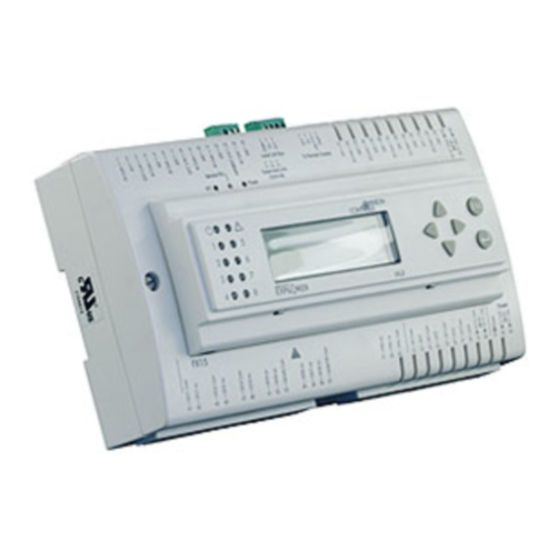
Introduction to FX15 Controller ............................................................ 3
Key Concepts ...................................................................................................... 4
FX15 Controller ................................................................................................................. 4
Installation .............................................................................................. 5
North American Emissions Compliance ............................................................................ 6
Detailed Procedures ........................................................................................... 7
Mounting Instructions ........................................................................................................ 7
Assembling the Integrated MUI......................................................................................... 8
Connection Details .......................................................................................................... 10
Connection Details for the N2 Open Card ...................................................................... 13
Connection Details for the L
Connection Details for the Remote User Interface ......................................................... 19
Connection Details for the FX Programming Key ........................................................... 22
Inputs and Outputs .............................................................................. 26
Introduction ....................................................................................................... 26
Key Concepts .................................................................................................... 27
Detailed Procedures ......................................................................................... 28
Isolation Diagram ............................................................................................................ 28
FX15 Controller I/Os Powered at 24 VAC ....................................................................... 29
Analog Inputs .................................................................................................................. 30
Digital Inputs ................................................................................................................... 36
Analog Outputs ............................................................................................................... 37
Digital Outputs ................................................................................................................ 39
Extension Modules ......................................................................................................... 42
Troubleshooting ................................................................................................ 44
Reading 9999 or Invalid from the Analog Inputs ............................................................. 44
Cannot Properly Read Current Sensors ......................................................................... 44
© 2014 Johnson Controls, Inc.
Code No. LIT-12011107
FX15 Controller
Card ................................................................... 17
Technical Bulletin FX15 Controller
Issue Date June 9, 2014
www.johnsoncontrols.com
1
Advertisement
Table of Contents

Related Manuals for Facility Explorer FX15

Summary of Contents for Facility Explorer FX15
-
Page 1: Table Of Contents
Introduction ....................... 26 Key Concepts ....................27 Detailed Procedures ..................28 Isolation Diagram ......................28 FX15 Controller I/Os Powered at 24 VAC ............... 29 Analog Inputs ........................30 Digital Inputs ........................36 Analog Outputs ....................... 37 Digital Outputs ........................ 39 Extension Modules ...................... - Page 2 Specifications and Technical Data ............. 50 Ordering Codes ....................50 Technical Specifications .................. 53 I/O Technical Details ....................... 53 N2 Open Card ......................... 55 Connection ....................55 ORKS Programming Key ......................56 FX15 Controller ....................... 56 FX15 Extended Range Controller ................... 57...
-
Page 3: Introduction To Fx15 Controller
For stand-alone applications an onboard, real-time clock circuit is also included to support the start-stop scheduling of equipment and real-time based control sequences. The FX15 controller can be integrated, as a slave device, in a distributed control application managed by a master controller (FX16 Master Controller or Master Display). -
Page 4: Key Concepts
FX15 Controller Technical Bulletin Optional accessories make the FX15 controller the state of the art solution for the HVACR market: • N2 Open plug-in communication card • plug-in communication card ORKS • user interface: Medium User Interface (MUI) and Large User... -
Page 5: Installation
FX15 Controller Technical Bulletin Installation This chapter describes the process of installing an FX15 controller. 66 (2.6) 179 (7.05) 49 (1.93) 215 (8.46) Figure 2: Mounting Dimensions for FX15 Controller, mm (in.) (Shown with Integral User Interface and Screw Connectors) 180.5 (7.11) -
Page 6: North American Emissions Compliance
FX15 Controller Technical Bulletin North American Emissions Compliance United States This equipment has been tested and found to comply with the limits for a Class A digital device pursuant to Part 15 of the FCC Rules. These limits are designed to provide reasonable protection against harmful interference when this equipment is operated in a commercial environment. -
Page 7: Detailed Procedures
FX15 Controller Technical Bulletin Detailed Procedures Follow these instructions to properly install and connect the FX15 controller. WARNING: Risk of Electric Shock. Disconnect or isolate all power supplies before making electrical connections. More than one disconnect or isolation may be required to completely de-energize equipment. Contact with components carrying hazardous voltage can cause electric shock and may result in severe personal injury or death. -
Page 8: Assembling The Integrated Mui
1. Remove the FX15 controller front cover screws. Figure 4: Open the FX15 Controller 2. Hook the display to the top of the FX15 controller cover. Figure 5: Display Installation 3. Push the display down until it locks into the FX15 controller. - Page 9 4. Open the FX15 controller. Figure 7: Open the FX15 Controller 5. Install the ribbon cable. Do not twist the ribbon cable; keep the ribbon cable flat. Figure 8: Ribbon Cable Installation 6. Close the FX15 controller and secure the two front cover screws.
-
Page 10: Connection Details
FX15 Controller Technical Bulletin Connection Details LP-FX15D2x and LP-FX15D7x Wiring Diagram Figure 9: Connection Details for the FX15 Controller (9 Relays) - Page 11 FX15 Controller Technical Bulletin LP-FX15D1x and LP-FX15D6x Wiring Diagram Figure 10: Connection Details for the FX15 Controller (5 Triacs and 4 Relays) Consider the following information when working with the connection details for the FX15 controller: • All commons are electrically dependent.
- Page 12 FX15 Controller Technical Bulletin Jumper Details AI2 AI3 AI4 AI5 1 2 3 Battery Figure 11: Jumper Connections Table 1: Jumper Connections Analog Input (AI) 0-20/4-20 mA Resistive, 0-10 V or Ratiometric AI1-AI6 Jumpers Closed Jumpers Open (Default configuration) Sensors Power Supply AVPS +5 V...
-
Page 13: Connection Details For I/O Expansion (Xt-Xp Modules) On Local Extension Bus
FX15 controller end only. Connection Details for the N2 Open Card The FX15 controller comes with the N2 Open card either installed or not installed. If the N2 Open card is not installed, you can install the N2... - Page 14 FX15 Controller Technical Bulletin The N2 Open plug-in serial card allows you to connect the FX15 controller to an N2 Open serial network through the RS-485 standard. Address Selection Figure 13: N2 Open Plug-in Communication Card Figure 14: N2 Open Card Connection...
- Page 15 FX15 Controller Technical Bulletin Figure 15: Open the Controller 3. Insert the card. See Figure 16. Align the pins as shown in figure. Figure 16: Insertion of the N2 Open Card 4. Set the address DIP switches. 5. Replace and close the lid.
- Page 16 FX15 Controller Technical Bulletin Address Selection Use the DIP switches (see Figure 13) to select the serial address of the FX15 controller in the N2 Open network. The address selection occurs in binary mode. Examples: • 1 ON, all others open address = 2 + …...
-
Page 17: On Works
ORKS card at a later time in the field. For details, see Ordering ORKS Codes. The L plug-in serial card allows you to connect the FX15 ORKS controller to a L network. ORKS Service PIN... - Page 18 FX15 Controller Technical Bulletin Figure 19: Open the Controller 3. Insert the card. See Figure 20. Align the pins as shown in figure. Figure 20: Insertion of the L Card ORKS 4. Replace and close the lid. IMPORTANT: The CMOS integrated circuit in the controller and on the communication card are sensitive to static current discharges.
-
Page 19: Connection Details For The Remote User Interface
The MUI is available in two models: panel mount (up to 3 m [9.8 ft]) and wall mount (up to 1 km [0.6 mi]). The FX15 controller can support one panel mount MUI plus one wall mount MUI, or two wall mount MUIs (see Figure 21 and Figure 22). - Page 20 FX15 Controller Technical Bulletin MUI-008_10 2002 Max 1 Km, total length MUI 1 MUI 2 FX15 To Power Supply To Power Supply 9 ÷ 48 VDC 9 ÷ 48 VDC 12 ÷ 24 VAC 12 ÷ 24 VAC FX15 "Universal"...
- Page 21 FX15 Controller Technical Bulletin Assigning the Medium User Interface’s N2 Address in Case of Multiple Connections At powerup, the MUI automatically has a default N2 address equal to 1. If you connect multiple MUIs, change the second MUI N2 Address to avoid communication conflicts.
-
Page 22: Connection Details For The Fx Programming Key
FX15 Controller Technical Bulletin Connection Details for the FX Programming Key Use the FX Programming Key to upload an application from a computer or from a preprogrammed FX15 controller, then download that application to other FX15 controllers. Upload Download Download / Upload... - Page 23 FX15 Controller Technical Bulletin Connecting the Programming Key to an FX15 Controller To connect the Programming Key to an FX15 controller: 1. Power off the controller. 2. Remove any connected user interfaces from the Remote Display Port (JP2). 3. Plug the Programming Key into the Display Port (JP2) (see Figure 26).
- Page 24 FX15 Controller Technical Bulletin Connecting the Programming Key to a Computer Figure 27: Programming Key Connection to a Computer To connect the Programming Key to a computer: 1. Connect the terminal adapter (included in the Programming Key kit) to the RS-232/485 converter connected to the computer.
- Page 25 The Programming Key memory is erased automatically when you use FX Loader. However, when an application is loaded from a computer, or when the application is loaded from another FX15 controller, you must manually perform erase the Programming Key memory.
-
Page 26: Inputs And Outputs
FX15 Controller Technical Bulletin Inputs and Outputs Introduction The FX15 controller features the following I/O Channels: • six high resolution Analog Inputs (AIs) (13 bit, A/D Converter) • eight opto-isolated Digital Inputs (DIs) from potential free contacts, each with transition counter •... -
Page 27: Key Concepts
Digital Inputs The FX15 controller accepts eight opto-isolated digital inputs from voltage-free contacts. Analog Outputs The FX15 controller provides up to four 0-10 VDC opto-isolated analog outputs. Digital Outputs The FX15 controller provides nine digital outputs, available in two hardware configurations with nine relays, or four relays and five triacs. -
Page 28: Detailed Procedures
FX15 Controller Technical Bulletin Detailed Procedures Isolation Diagram Figure 29: Insulation Diagram (*) Opto-isolated (maximum 500 V) if an additional separated power supply is used (**) Not isolated (***) DC/DC converted with dielectric strength up to 1000 V... -
Page 29: Fx15 Controller I/Os Powered At 24 Vac
15 VA Figure 30: Powering FX15 Controller I/Os To maintain the insulation between the FX15 controller power supply and the I/Os, run the power supply cable while respecting the polarity as shown in Figure 30, and add an External Protection fuse (2 A) to avoid incorrect wiring. -
Page 30: Analog Inputs
For these sensors, the measurement range is fixed. You can set the reliability range via software. The read signal is converted by the FX15 controller according to the related Analog Input object setup. Available setups are: • Linear 0-10 V •... - Page 31 • Concentration • Ampere • Voltage A configurable filter constant in seconds is performed by the FX15 controller on its Analog Inputs for the reduction of signal instability. You can configure an additional Anti-Spike filter to limit the rate of change of the input values to the value indicated by this attribute.
- Page 32 Figure 32: Active 0-10 V Probe, Connection Diagram The inputs must be configured to accept 0-10 V signals by the application software in the FX15 controller. The AI Jumpers must be opened (factory default setting) to accept voltage inputs. Table 4: Active 0-10 V Sensors...
- Page 33 FX15 Controller Technical Bulletin Connecting Passive Resistive Sensors The FX15 controller analog inputs accept linear resistive signals as the Resistive 2k ohm. The Analog Input software can also linearize signals provided by the most common sensors as Ni1000, A99, Pt1000, and NTC 2k2.
- Page 34 FX15 Controller Technical Bulletin Connecting Active Current Sensors The FX15 controller analog inputs can accept a maximum of four active current sensors, powered by the FX15 controller itself, in the range 0-20 mA or 4-20 mA. The AI has to be configured via software (and hardware jumpers) to accept current signals.
- Page 35 FX15 Controller Technical Bulletin Connecting Active Sensors Powered by 24 VAC The FX15 can accept active temperature, pressure, flow, and humidity sensors providing 0-10 V or current signals powered by 24 VAC. A second transformer (24 VAC/24 VAC, 3 VA maximum) powering only the Analog Input is required to maintain the insulation from the microprocessor.
-
Page 36: Digital Inputs
The default setting is Direct, meaning it is active (true) when closed. See I/O Technical Details for the complete FX15 controller I/O table. Digital Inputs Powered by 24 VAC The eight FX15 controller Digital Inputs must be 24 V powered (through terminals 34 and 35). -
Page 37: Analog Outputs
The numbers inside the parentheses are the FX15 controller terminal numbers. Using Analog Inputs as Digital Inputs If you need more than 8 digital inputs, the FX15 controller allows you to use an analog input as a digital input. FX15... - Page 38 FX15 Controller Technical Bulletin The FX15 controller analog outputs are commonly used to drive proportional devices and can be connected to all the Johnson Controls Proportional Valve Actuators (Figure 38). FX15 FX16 15 VA 24 Vac 220Vac Figure 38: Connecting the Analog Output without Opto-isolation IMPORTANT: Maintain proper polarity and voltage or current ratings.
-
Page 39: Digital Outputs
The numbers inside the parentheses are the FX15 controller terminal numbers. Digital Outputs The FX15 controller features nine digital outputs, available in two hardware configurations: all nine relays, or four relays and five triacs. Use the application software to configure the Digital Outputs for direct acting or reverse acting. - Page 40 FX15 Controller Technical Bulletin Connecting the Relays The FX15 controller features up to nine Digital Outputs with electromechanical relays. To simplify assembly, the common terminals of some relays have been grouped together. The relays are divided into six groups, according to the distance of insulation.
- Page 41 Connecting the Triacs The FX15 controller triac (0.5 A, 24 VAC) digital outputs are commonly used to operate in Position Adjust Type (PAT) and Duration Adjust Type (DAT) modes.
-
Page 42: Extension Modules
The numbers inside the parentheses are the FX15 controller terminal numbers. Extension Modules The input/output capacity of the FX15 controller may be extended by connecting up to four extension modules via the Extension Bus (XT-Bus, terminal J1). An extension module is formed by an XT91D00 processor/communications module and one or more XP expansion modules. - Page 43 FX15 Controller Technical Bulletin Analog outputs in extension modules can be configured to provide 0-10 V, 0-20 mA or 4-20 mA signals. The output has low range and high range variables to provide a 0-100% signal to the extension module.
-
Page 44: Troubleshooting
FX15 Controller Technical Bulletin Troubleshooting Reading 9999 or Invalid from the Analog Inputs • Error/Condition: The Analog Input object retrieves an Invalid value through network variables, or the User Interface Unit shows 9999 or an Invalid customized tag. • Problem: Happens when the signal applied to the Analog Input channel does not match with the one configured via software on the Analog Input Object. -
Page 45: Operation
FX15 Controller Technical Bulletin Operation Introduction The FX15 controller is a high-performance field controller and has been designed to respond to a wide range of applications, including dual compressor chillers and rooftops, close control units, packaged air handling units, unit vents, and water source heat pumps. -
Page 46: Alarm And Event Management
ORKS Alarm and Event Management The FX15 controller manages and records events or alarms that are associated with data points or variables in the control application. The table of active events and the event history log may be viewed on the user interfaces. -
Page 47: User Interface
FX15 Controller Technical Bulletin User Interface The FX15 controller can be connected to two remote user interfaces, with the capability to display/edit all the data point and information of the running application. The user interface application is fully configurable at design time. The user interface must be of the same type. - Page 48 FX15 Controller Technical Bulletin Figure 45 : Large User Interface (LUI) • LP-DIS60U10-C: Integrated Medium User Interface, Integrated, 4x20 backlit Lighting Control Data (LCD), IP54, and extended temperature range of -20°C (68°F) to 50°C (122°F). Figure 46 : Integrated Medium User Interface (MUI) •...
-
Page 49: Security
FX15 Controller Technical Bulletin Security The FX Tools Pro and the Facility Explorer controllers come with an embedded security feature based on the use of two IDs: the Family ID and the Customer ID. Family ID Family ID differentiates hardware types and prevents the downloading of the wrong application to the wrong controller. -
Page 50: Specifications And Technical Data
Ordering Codes Description LP-FX15D10-000C FX15 controller, 4 relays and 5 triacs, without the application LP-FX15D11-000C FX15 controller, 4 relays and 5 triacs, N2 Open card preassembled, without the application LP-FX15D12-000C FX15 controller, 4 relays and 5 triacs, L card preassembled, without... - Page 51 Integrated MUI, (4x20) LCD backlit display for FX15 controller Table 13: Accessories Ordering Codes Description LP-KIT007-000C Link cable for the connection of the FX15 controller to the MUI/LUI display, 3 m (10 ft) LP-KIT007-020C Kit of five replacement communication wiring connectors LP-KIT015-000C...
- Page 52 FX15 Controller Technical Bulletin Table 15: Room Command Modules Available Only in North America Ordering Codes Description LP-KIT006-004C Room Sensor module for FX05, warm/cool adjustment dial, occupancy button, fan speed selector switch, service port, US mounting kit LP-KIT006-005C Room Sensor module for FX05 warm/cool adjustment dial, occupancy button,...
-
Page 53: Technical Specifications
FX15 Controller Technical Bulletin Technical Specifications I/O Technical Details Table 18: Analog Input (AI) Terminals Channel Type Remark/Application TB1 (1-15) AI1, AI2, AI3, AI4, AI5, AI6 See Figure 30. Software configurable. Application: temperature, humidity, pressure TB1 (3, 8) EXT-VDC +16 V, 80 mA Directly power from the controller. - Page 54 FX15 Controller Technical Bulletin Table 20: Digital Output (DO) Terminals Channel Type Remark/Application DO1, DO2, DO3 SPST 8(3)A power relays Maximum switching power: 2000VA, 240W, 0.5HP, 250 VAC UL/CUR rating: 8A 250 VAC 8A 30 VDC VDE rating: 8A 250 VAC Expected electrical life min.
-
Page 55: N2 Open Card
FX15 Controller Technical Bulletin N2 Open Card Table 22: N2 Open Card RS-485 line Maximum length without repeater: 1,200 m (4,000 ft), AWG26 twisted pair with shield. Devices Maximum of 32 per 1,200 m (4,000 ft) bus segment. RS-485/232 Converter... -
Page 56: Programming Key
Programming Key Table 24: Programming Key Power Supply Directly powered from the Display Bus port of the FX15 controller or from an AC/DC adapter 230 V to 12 VAC ÷ 15 VDC min 2 VA Memory type and size Flash memory 1 MB Connection to controller Via RS-485, not isolated, 10 cm (3.9 in.) cable provided with the key... -
Page 57: Fx15 Extended Range Controller
Display and Extensions cable type Belden 4-core, twisted pair, shielded Compliance Europe CE Mark – Johnson Controls, Inc., declares that the FX15 Controllers are in compliance with the essential requirements and other relevant provisions of the EMC Directive 2004/108/EC and the Low Voltage Directive 2006/95/EC. - Page 58 Belden 4-core, twisted pair, shielded Compliance Europe CE Mark – Johnson Controls, Inc., declares that the FX15 Extended Range Controllers are in compliance with the essential requirements and other relevant provisions of the EMC Directive 2004/108/EC and the Low Voltage Directive 2006/95/EC.
Need help?
Do you have a question about the FX15 and is the answer not in the manual?
Questions and answers