
Related Manuals for UUGear Witty Pi 4 L3V7

Summary of Contents for UUGear Witty Pi 4 L3V7
- Page 1 Witty Pi 4 L3V7: Realtime Clock and Power Management for Raspberry Pi User Manual (revision 1.01) Copyright © 2022 Dun Cat B.V., All rights reserved. UUGear is a trade name of Dun Cat B.V.
-
Page 2: Table Of Contents
Install Software ......................7 Update Software ......................8 Uninstall Software ...................... 8 Mounting Witty Pi 4 L3V7 on Raspberry Pi ................9 Mounting Witty Pi 4 L3V7 on Raspberry Pi Zero............9 Mounting Witty Pi4 Mini on Other Raspberry Pi Models ......... 10 Software Usage ........................ - Page 3 Witty Pi Log Files ......................32 Frequently Asked Questions (FAQ) ................. 33 14.1 What I2C address is used by Witty Pi 4 L3V7? Can I change it? ......33 14.2 What I C Registers are provided by Witty Pi 4 L3V7? ..........34 14.3...
- Page 4 14.5 Witty Pi 4 L3V7 does not boot? ................42 14.6 Why Raspberry Pi Immediately Turns On after Shutdown? ........45 Revision History ....................... 47 Copyright © 2022 Dun Cat B.V., All rights reserved. UUGear is a trade name of Dun Cat B.V.
-
Page 5: Product Overview
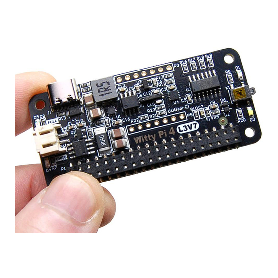
Raspberry Pi’s ON/OFF sequence, and significantly reduce the energy usage. Witty Pi 4 L3V7 is the new member of the fourth generation of Witty Pi, and it is designed to work with 3.7V Lithium (ion or polymer) battery (that’s what L3V7 stands for), and can be used as an UPS. -
Page 6: Built-In Uninterruptible Power Supply (Ups) Functionality
Lithium Ion or Lithium Polymer battery that has nominal voltage of 3.7V (and full-charged voltage of 4.2V). When 5V power supply is connected to the USB-C connector on Witty Pi 4 L3V7, it will take the priority to power the board with Raspberry Pi together. In the meantime, the battery is disconnected from the power rails and gets charged. -
Page 7: Temperature Controlled Device
Witty Pi installed. 1.3 Temperature Controlled Device The temperature sensor on Witty Pi 4 L3V7 has 0.125 °C resolution. The temperature data is used for compensating the crystal and make the RTC more accurate. -
Page 8: E-Latching Power Switch
1.5 Interface Introduction Witty Pi 4 L3V7 supports all Raspberry Pi models that has the 40-pin GPIO header, including A+, B+, 2B, Zero, Zero W, Zero 2 W, 3B, 3B+, 3A+ and 4B. You will need to solder the 40-pin header to Zero/Zero W/Zero 2 W model beforehand, so they can make reliable connection with Witty Pi. -
Page 9: Specification / Technical Details
Operating Temperature -30°C~80°C (-22°F~176°F) Environment Humidity 0~80%RH, no condensing, no corrosive gas 3. Package Content Each package of Witty Pi 4 L3V7 contains: ⚫ Witty Pi 4 L3V7 board x 1 ⚫ M2.5 x 10mm plastic screws x 4 4mm plastic spacer x 4 ⚫... -
Page 10: How Does Witty Pi Work
Witty Pi has Analogue to Digital Converter (ADC) in its microcontroller (MCU), which can measure the input voltage (V Witty Pi 4 L3V7’s design is a little different from Witty Pi 4 and Witty Pi 4 Mini, that the battery voltage and 5V from USB-C merge into the input voltage (V ). -
Page 11: Software Installation, Updating And Uninstallation
Battery In Witty Pi 4 L3V7, you can configure the low voltage threshold. If the input voltage drops below the preset threshold, Witty Pi’s firmware will emulate a “button clicking” to turn off your Raspberry Pi. -
Page 12: Update Software
5.2 Update Software If there is a newer version of software and you want to install it, in most of the time you just need to repeat the installation process and let it overwrite your current version. If you prefer, you can also fully uninstall the software (please see below) and then install it again. 5.3 Uninstall Software To uninstall the software, you need to remove the “wittypi”... -
Page 13: Mounting Witty Pi 4 L3V7 On Raspberry Pi
6.1 Mounting Witty Pi 4 L3V7 on Raspberry Pi Zero If you want to use Witty Pi 4 L3V7 on Raspberry Pi Zero (V1.2, V1.3, W and 2W), you will need to solder the 20x2 pin male header on it first, or you can buy one with the header soldered already. -
Page 14: Mounting Witty Pi4 Mini On Other Raspberry Pi Models
Witty Pi 4 L3V7 (as shown in figure above). You can then place a steel ruler (or something similar) between the two rows of pins and push Witty Pi 4 L3V7 down until it reaches the plastic of the... - Page 15 Now your Witty Pi 4 L3V7 is ready to go. If you want to take off the stacking header from Witty Pi 4 L3V7, the proper way is to put your Witty Pi 4 L3V7 up-side-down, and let the 40 pins contact a flat surface (e.g. desktop), hold the two edges of the board and press down.
-
Page 16: Software Usage
./wittyPi.sh ================================================================================ Witty Pi - Realtime Clock + Power Management for Raspberry Pi < Version 4.10 > by Dun Cat B.V. (UUGear) ================================================================================ >>> Current temperature: 35.625°C / 96.125°F >>> Your system time is: 2022-11-15 11:14:18 CEST >>> Your RTC time is: 2022-11-15 11:14:18 CEST >>>... -
Page 17: Write Rtc Time To System
option should be used when you find the Raspberry Pi system time is correct (may be synchronized from the Internet) while the RTC time is not correct. 7.2 Write RTC time to system This option will copy the time from the Realtime Clock on Witty Pi to your Raspberry Pi system. This option should be used when you find the RTC time is correct while the system time is not correct. -
Page 18: Set Low Voltage Threshold
7.8 Auto-On when USB 5V is connected This is a switch to decide whether Witty Pi 4 L3V7 will turn on Raspberry Pi, when USB-C 5V power supply is connected (no matter the battery is connected or not). This switch is turned on by default. - Page 19 You may set a value between 0 and 255 here. If you are using a power bank to provide 5V to the USB-C connector on Witty Pi 4 L3V7, in the majority of cases you don’t need the (pulsing) dummy load: if the battery is being charged, it will draw enough current from the power bank and keep the power bank awake;...
-
Page 20: Reset Data
resistor. You can configure this parameter to adjust the result of output current calculation. The default value is set to 0.00A, and you can input a value between -1.27 and 1.27 here. • Default ON delay If you have configured the default state when powered to “ON”, this option allows you to specify a delay (in seconds) before Witty Pi automatically turns on Raspberry Pi. -
Page 21: Using Uwi (Uugear Web Interface)
“diagnose.sh” script in “uwi” directory to do so automatically. pi@raspberrypi:~/uwi $ ./diagnose.sh In UWI, your Witty Pi 4 L3V7 device is presented like this: Here you can monitor and control your Witty Pi 4 L3V7 device like using a website. -
Page 22: About Schedule Script
9. About Schedule Script Besides manually schedule the next shutdown/startup time, you can also use a schedule script to plan the ON/OFF sequence for your Raspberry Pi. A schedule script is a text file with .wpi file extension. Witty Pi’s software will load and execute it automatically after Raspberry Pi is boot up. 9.1 How does Schedule Script Work? A schedule script defines a loop, and it put a serial of ON/OFF states into it. - Page 23 Please keep in mind that, running the same schedule script at different moment may get different result, as the “runScript.sh” will search and find the proper state according to current time. When the “runScript.sh” is executed, if the current time is located at an “OFF” state instead, it will take the next “ON”...
-
Page 24: Make Your Own Schedule Script
9.2 Make Your Own Schedule Script A schedule script is actually a text file, and you can use any text editor to create and edit it. Below is a very simple schedule script and it will keep your Raspberry Pi on for 5 minutes in every 20 minutes. - Page 25 Sometimes you may want to skip certain scheduling of shutdown/startup, and let your own program to do the job. This can be achieved by using the WAIT syntax. For example: M15 WAIT This will keep your Raspberry Pi ON and no shutdown will be scheduled after 15 minutes, because there is a WAIT at the end of the line.
-
Page 26: Using Schedule Script Generator
You can also use our web application to create your schedule script. Just simply open this URL in your web browser: https://www.uugear.com/app/wittypi-scriptgen/ This web application allows you to visually create the schedule script, and it immediately generate the final code on the right. -
Page 27: Advanced Usage Of Schedule Script
9.4 Advanced Usage of Schedule Script Besides choosing the schedule script from wittyPi.sh, you can also use schedule script without the help from wittyPi.sh. Just copy the schedule script file to “~/wittypi/schedule.wpi” and then run “./runScript.sh” in the “~/wittypi” directory, the script will start to work. This allows you to use schedule script as an interface, to integrate other tools with Witty Pi together. -
Page 28: Know More About The Realtime Clock
10.1 No Off-Power Time Keeping Different from Witty Pi 4 and Witty Pi 4 Mini, Witty Pi 4 L3V7 doesn’t come with battery or super capacitor for off-power time keeping. This is because Witty Pi 4 L3V7 is supposed to have battery connected. - Page 29 Temperature - Frequency Error ºC The orange curve is the actual measured temperature – frequency error curve. Witty Pi 4 L3V7’s firmware uses the green four-segment line to approximate the actual curve for temperature compensation.
-
Page 30: Additional Interfaces
11. Additional Interfaces 11.1 The 3 Pads for Power Connection (P2 on the back) On the back of Witty Pi 4 L3V7 board, there are three big pads for power connection. They are BAT (battery), GND and 5V (links to USB). - Page 31 SW / SWITCH It is the signal line that connects to the switch (button) on Witty Pi 4 L3V7. It is also directly connected to GPIO-4 in Raspberry Pi’s GPIO header. If you want to connect your own (2-lead) switch, you may wire the two leads to SWITCH/GPIO-4 and GND pins.
-
Page 32: The Unpopulated 2 X 3 Pin Headers (P4)
/ 0.05 = 20 * V It is the ground of Witty Pi 4 L3V7 board, and it directly connects to the GND wire of power supply. 11.3 The Unpopulated 2 x 3 Pin Headers (P4) This is the In-Circuit Serial Programming (ICSP) header for uploading the firmware to the micro controller. -
Page 33: The Unpopulated 7-Pin Header In The Middle (P5)
These are the SCL and SDA for internal I2C bus. The RTC and temperature sensor are directly connected to this internal I2C bus. It is the ground of Witty Pi 4 L3V7 board, and it directly connects to the GND wire of power supply. -
Page 34: Integrate With Other Programs
12. Integrate with Other Programs Witty Pi’s software is written in BASH, and it is very easy to modify and integrate with other programs. The daemon.sh script is registered to be executed after boot, and this registration was done by the installation script (using update-rc.d command). - Page 35 [ "$(/usr/bin/hostname -I)" = "" ]; do /usr/bin/sleep 1 done /usr/bin/wget "https://www.uugear.com/” >/home/pi/wittypi/wget.log 2>&1 This code snippet waits for network and then query the webpage from UUGear’s website. Please notice the full path for commands and files. hostname → /usr/bin/hostname sleep → /usr/bin/sleep wget →...
-
Page 36: Witty Pi Log Files
13. Witty Pi Log Files In the directory that you install your Witty Pi software, you can find two log files: schedule.log wittyPi.log. If you need our help for solving a problem, please kindly put the log files in email attachment too. -
Page 37: Frequently Asked Questions (Faq)
C address: 0x08. This address is configurable and you can change it if you want. If you have Witty Pi 4 L3V7 connected to Raspberry Pi and run “i2cdetect –y 1” command in the console, you will see this: pi@raspberrypi:~ $... -
Page 38: What I C Registers Are Provided By Witty Pi 4 L3V7
C registers • Virtual I C registers The table below shows the registers provided by Witty Pi 4 L3V7. As you can see, some of them are read-only (cannot be changed, or can only be updated by the firmware itself):... - Page 39 Index Description Range Default Accessible Firmware ID 0x37 Read-only Integer part for input voltage 0~255 Read-only Decimal part (multiple 100 times) for input 0~99 Read-only voltage Integer part for output voltage 0~255 Read-only Decimal part (multiple 100 times) for output 0~99 Read-only voltage...
- Page 40 The reason code for latest action. Read-only • 0 = N/A • 1 = ALARM1 • 2 = ALARM2 • 3 = Button is clicked • 4 = Input voltage too low • 5 = Input voltage is restored • 6 = over temperature •...
- Page 41 up the white LED The delay (multiple 10) before power cut: 0~255 Read & Write default=50 (5 seconds) Recovery voltage threshold (multiple 10, 0~255 Read & Write 255=disabled) Dummy load duration. 0 if dummy load is off. 0~255 Read & Write The bigger value, the longer time for dummy load to draw current Adjustment for measured input voltage (multiple...
- Page 42 format Standard value for RTC offset -127~127 Read & Write Turn on/off temperature compensation. 0 or 1 Read & Write • ON = 1 • OFF = 0 A flag that indicates ALARM1 (startup) is 0 or 1 Read & Write triggered and not processed.
- Page 43 Reserved for future usage #5 0~255 Read & Write Reserved for future usage #6 0~255 Read & Write LM75B: temperature register (2 bytes) Read-only LM75B: configuration register 0~255 Read & Write LM75B: hysteresis temperature register (2 bytes) Read & Write LM75B: overtemperature register (2 bytes) Read &...
- Page 44 You will need to modify the software accordingly, and reconnect the power supply to make it work. You can find more details in the “What I2C address is used by Witty Pi 4 L3V7? Can I change it?” section.
-
Page 45: What Gpio Pins Are Used By Witty Pi4 L3V7
Witty Pi uses GPIO-4 to monitor the button action, and its software uses GPIO-17 to send out the SYS_UP signal to Witty Pi when the system is up. Witty Pi 4 L3V7 use GPIO-5 and GPIO-6 to check the status of the charging module. GPIO-5 will be... -
Page 46: Is Witty Pi 4 L3V7 Compatible With "Other Hardware
Please understand that we might not have the hardware you refer, and even if we have, it is difficult for us to make tests on all those hardware with Witty Pi 4 L3V7. Fortunately, it is not that difficult to figure out the answer by yourself. - Page 47 • 1-Wire interface should be disabled if you don’t need it, or you need to assign a GPIO pin other than GPIO-4 to it. If your Raspbian (Raspberry Pi OS) has GUI installed, you can review/configure these interfaces via Raspberry Pi Configuration: Also, you can check all GPIO pin states with the command below.
- Page 48 There are some possible reasons that can cause this kind of problem: 1. You are using NOOBS NOOBS is not always causing this kind of problem, but the chance does exist. If you installed multiple operating systems into your Pi, the chance that NOOBS causes this problem will increase. If possible, please try not to use NOOBS.
- Page 49 #dtoverlay=w1-gpio Save the file and eject your micro SD card, and put it back to your Raspberry Pi. Now your Raspberry Pi should be able to boot normally. 3. Serial Port is not properly configured The serial port (UART0) should be enabled, and it should be on GPIO-14 and GPIO-15 (BCM naming). The TXD pin in serial port will be monitored by Witty Pi and it goes to LOW when the system has been shut down.
- Page 50 request and will turn on Raspberry Pi just after it gets power off. This scenario may happen when your Raspberry Pi’s TXD pin does not go LOW after system has been shut down. The reason could be some other hardware strongly pulls up TXD pin, or the system crashed during shutdown.
- Page 51 15. Revision History Revision Date Description 1.00 2022.11.28 Initial revision 1.01 2022.12.28 Add declaration that software is developed and tested under Raspbian.
Need help?
Do you have a question about the Witty Pi 4 L3V7 and is the answer not in the manual?
Questions and answers