Table of Contents
Advertisement
EN
2
Manual No. FIL.SILOTOP_zero.--.M.A4.0722.EN
WAMGROUP S.p.A.
Via Cavour, 338
I-41030 Ponte Motta
Cavezzo (MO) - ITALY
SILO VENTING FILTERS
ASSEMBLY AND
MAIN INSTRUCTIONS
FOR USE AND
MAINTENANCE
Latest update: July 2022
ORIGINAL INSTRUCTIONS IN ENGLISH
Issue: A4
+ 39 / 0535 / 618111
fax
+ 39 / 0535 / 618226
e-mail
info@wamgroup.com
internet
www.wamgroup.com
Advertisement
Table of Contents

Summary of Contents for WAM SILOTOP zero
- Page 1 SILO VENTING FILTERS ASSEMBLY AND MAIN INSTRUCTIONS FOR USE AND MAINTENANCE Manual No. FIL.SILOTOP_zero.--.M.A4.0722.EN Issue: A4 Latest update: July 2022 ORIGINAL INSTRUCTIONS IN ENGLISH WAMGROUP S.p.A. + 39 / 0535 / 618111 Via Cavour, 338 + 39 / 0535 / 618226 I-41030 Ponte Motta e-mail info@wamgroup.com...
- Page 2 All the products described in this catalogue are manufactured according to WAMGROUP S.p.A. Quality System procedures. The Company’s Quality System, certified in July 1994 according to International Standards UNI EN ISO 9002 and extended to the latest release of UNI EN ISO 9001, ensures that the entire production process, starting from the processing of the order to the technical service after delivery, is carried out in a controlled manner that guarantees the quality standard of the product.
-
Page 3: Table Of Contents
07.22 INDEX FIL.SILOTOP_zero.--.M.A4.0722.EN Issue: A4 TABLE OF CONTENTS 1.0 GENERAL INFORMATION ........................1 1.1 Scope of the Manual .........................1 1.2 Symbols ............................2 1.3 Glossary and terminology .........................4 1.4 Manufacturer’s data and identification of equipment ................. 5 1.5 Request for assistance ........................6 1.6 Warranty ............................6 1.7 Exclusion of responsibility .........................6 2.0 INFORMATION REGARDING SAFETY ....................7... - Page 4 07.22 INDEX FIL.SILOTOP_zero.--.M.A4.0722.EN Issue: A4 6.0 INFORMATION REGARDING USE .......................29 6.1 Production Start-up .........................29 6.2 Machine shut-down at the end of the work cycle ................29 6.3 Long shut-downs of the equipment ....................30 6.4 Reuse after long shut-down ......................30 7.0 INFORMATION REGARDING MAINTENANCE ..................31 7.1 Periodic checking ..........................31 7.2 Cleaning the equipment (the machine) ...................36 7.3 Replacing the filter elements ......................36...
-
Page 5: General Information
07.22 1.0 GENERAL INFORMATION FIL.SILOTOP_zero.--.M.A4.0722.EN Issue: A4 1.1 Scope of the Manual This Manual has been prepared by the Manufacturer to provide the operating technical information for instal- lation, operation and maintenance of the equipment concerned. The Manual, which is an integral part of the equipment concerned, must be preserved throughout the life of the equipment in a known easily accessible place, available for consultation whenever required. -
Page 6: Symbols
07.22 1.0 GENERAL INFORMATION FIL.SILOTOP_zero.--.M.A4.0722.EN Issue: A4 1.2 Symbols To highlight certain parts of the text, for purposes of safety, or to indicate important information, certain symbols are used, the meaning of which is described below. It is important to comply with and scrupulously follow the information highlighted by the symbols. Danger - Warning Indicates situations of serious danger which, if ignored, can be risky for the health and safety of per- sons. - Page 7 07.22 1.0 GENERAL INFORMATION FIL.SILOTOP_zero.--.M.A4.0722.EN Issue: A4 List of safety and information symbols Symbol Symbol description representation Danger sign: indicates danger of electric shock caused by the presence of powered components inside the junction box or control panel. Obligation: read this Manual before carrying out any action on the equipment con- cerned.
-
Page 8: Glossary And Terminology
07.22 1.0 GENERAL INFORMATION FIL.SILOTOP_zero.--.M.A4.0722.EN Issue: A4 1.3 Glossary and terminology Operator: person appropriately trained and authorized by the Production Manager for setting up the equip- ment concerned and carrying out routine maintenance. Installer: organization with specialized technicians and appropriate equipment for carrying out risk-free instal- lation and extraordinary maintenance. -
Page 9: Manufacturer's Data And Identification Of Equipment
07.22 1.0 GENERAL INFORMATION FIL.SILOTOP_zero.--.M.A4.0722.EN Issue: A4 1.4 Manufacturer’s data and identification of equipment Important Do not change the data on the identification plate. Keep ID plates clean, intact and legible. If an ID plate is damaged or no longer legible (even if only one piece of information on it) contact the Manufacturer and ask for a new ID plate and replace it. -
Page 10: Request For Assistance
07.22 1.0 GENERAL INFORMATION FIL.SILOTOP_zero.--.M.A4.0722.EN Issue: A4 1.5 Request for assistance For all technical assistance, contact the Manufacturer’s service network. For all requests, provide the equipment identification data, the type of problem encountered and all other infor- mation which could be useful for identifying the problem. 1.6 Warranty The conditions for validity and applicability of the warranty are specified in the sales contract. -
Page 11: Information Regarding Safety
07.22 2.0 INFORMATION REGARDING SAFETY FIL.SILOTOP_zero.--.M.A4.0722.EN Issue: A4 2.1 General safety prescriptions Read the Instruction Manual carefully and strictly follow the instructions it includes, especially those regarding safety. Most accidents at the workplace are caused by negligence, failure to follow the most elementary safety regulations and incorrect or improper use of tools and equipment. -
Page 12: Safety Prescriptions For Installation
07.22 2.0 INFORMATION REGARDING SAFETY FIL.SILOTOP_zero.--.M.A4.0722.EN Issue: A4 2.3 Safety prescriptions for installation Before starting with installation, a “Safety Plan” must be implemented to safeguard the personnel di- rectly involved and those who carry out operations in the surrounding area. All the laws must be strictly applied, especially those concerning workplace safety. -
Page 13: Safety Recommendations On Biological Risks
07.22 2.0 INFORMATION REGARDING SAFETY FIL.SILOTOP_zero.--.M.A4.0722.EN Issue: A4 Apart from invalidation of the warranty, the Manufacturer declines all responsibility for damage to objects and harm to persons deriving from the use of non-original spare parts or due to modifications made during repairs without express written authorization. Use the oil and lubricants recommended by the Manufacturer. -
Page 14: Technical Information
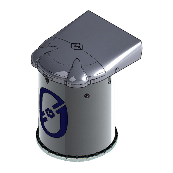
07.22 3.0 TECHNICAL INFORMATION FIL.SILOTOP_zero.--.M.A4.0722.EN Issue: A4 3.1 General description of the equipment SILOTOP zero is a cylindrically-shaped filter for the de-dusting (venting) of pneumatically loaded silos. ® The stainless steel casing contains vertically mounted POLYPLEAT filter elements. The automatic com- ®... -
Page 15: Main Components
07.22 3.0 TECHNICAL INFORMATION FIL.SILOTOP_zero.--.M.A4.0722.EN Issue: A4 3.2 Main components 1) Filter casing 6) Condensation drain tap 2) Seal frame 7) Filter cover 3) Air tank 8) POLYPLEAT filter elements ® 4) Solenoid valves 9) FILCONTROL 5) Blowing tubes... -
Page 16: Operating Principle
07.22 3.0 TECHNICAL INFORMATION FIL.SILOTOP_zero.--.M.A4.0722.EN Issue: A4 3.3 Operating principle The dirty air enters the filter body (1), where dust is separated by the filter elements (8). The compressed air pulse-jet cleaning system (3+4+5) removes the dust collected by the filter elements; then, the dust drops back inside the silo. -
Page 17: Noise Level
07.22 3.0 TECHNICAL INFORMATION FIL.SILOTOP_zero.--.M.A4.0722.EN Issue: A4 3.6 Noise level The noise level of the SILOTOP zero filter does not exceed the limit of the 2003/10/CE and 2006/42/CE Di- ® rectives. The measured equivalent continuous average sound pressure level LAeq is 70.0 dB(A). All readings were make using a precision sound level meter placed at 1 metre distance from the equipment and at 1.6 metres from ground, with compressed air shots at 6 bar each 28 seconds. -
Page 18: Safety And Information Signs
07.22 3.0 TECHNICAL INFORMATION FIL.SILOTOP_zero.--.M.A4.0722.EN Issue: A4 3.9 Safety and information signs Danger - Warning Follow the signs on plates. Ensure the plates are legible; otherwise clean them and replace the damaged ones, applying them in their original position. A) Danger sign: indicates danger of electric shock caused by the presence of powered components inside the junction box or control panel. -
Page 19: Information Regarding Handling And Transport
07.22 4.0 INFORMATION REGARDING HANDLING AND TRANSPORT FIL.SILOTOP_zero.--.M.A4.0722.EN Issue: A4 4.1 Type of packaging The filter is supplied on a pallet, protected by a wooden crate. WAM s.p.a. CAVEZZO ØB WEIGHT INCLUDING THE WOODEN CRATE ø B (KG) SILAB14 1000... -
Page 20: Reception Of Goods
07.22 4.0 INFORMATION REGARDING HANDLING AND TRANSPORT FIL.SILOTOP_zero.--.M.A4.0722.EN Issue: A4 4.2 Reception of goods On receiving the goods, ensure that the type and quantity correspond to the data present on the acknowledge- ment of order. Possible damage has to be immediately communicated in writing in the space provided to this purpose in the waybill. - Page 21 07.22 4.0 INFORMATION REGARDING HANDLING AND TRANSPORT FIL.SILOTOP_zero.--.M.A4.0722.EN Issue: A4 Lifting the filter Lift and handle the machines only by the eyelets provided for the purpose. Use lifting systems suitable for the weights, dimensions and movements to be carried out. Hook to the filter by means of the safety hooks. DO NO T use clamps, rings, open hooks or systems that do not ensure the necessary safety level.
-
Page 22: Installation And Fixing
07.22 5.0 INSTALLATION AND FIXING FIL.SILOTOP_zero.--.M.A4.0722.EN Issue: A4 5.1 Safety prescriptions for installation Danger - Warning The replacement operations must be carried out by a specialist authorized technician with specific skills. Provide appropriate safety measures and use suitable equipment to prevent risk of work accident to persons involved in the operations and to those nearby. - Page 23 07.22 5.0 INSTALLATION AND FIXING FIL.SILOTOP_zero.--.M.A4.0722.EN Issue: A4 The equipment supplied is provided with perimeter seal to be inserted between the filter and the bottom ring. Tighten the bolts by applying a torque of 10 Nm. Seal Positioning the seal Filter body •...
-
Page 24: Positioning The Filter Flange
07.22 5.0 INSTALLATION AND FIXING FIL.SILOTOP_zero.--.M.A4.0722.EN Issue: A4 5.2 Positioning the filter flange “A” Spot welding View from “A” Checking the circularity End of the welding... -
Page 25: Electronic Board - Connections And Settings
07.22 5.0 INSTALLATION AND FIXING FIL.SILOTOP_zero.--.M.A4.0722.EN Issue: A4 5.3 Electronic board - connections and settings For the electrical connection and settings of the new Filcontrol time and Filcontrol Connect electronic boards, refer to the related manual (file name ELECTRONIC BOARDS FILCONTROL - it.pdf) available in the Down- load section of the page dedicated to the WAMFLO Flanged Round Dust Collectors on wamgroup.com. -
Page 26: Pneumatic Connection
07.22 5.0 INSTALLATION AND FIXING FIL.SILOTOP_zero.--.M.A4.0722.EN Issue: A4 5.5 Pneumatic connection The compressed air must be: 1) Clean: with no residues that might damage the filter. Danger - Warning Drain the piping prior to connecting the compressed air to the filter. 2) De-moist- The air tank is provided with a condensate drainage tap. - Page 27 5.0 INSTALLATION AND FIXING FIL.SILOTOP_zero.--.M.A4.0722.EN Issue: A4 USCITA ARIA AIR OUTLET ENTRATA ARIA AIR INLET CODES DESCRIPTION MANUAL BALL VALVE (NOT SUPPLIED BY WAM ® RELIEF VALVE (NOT SUPPLIED BY WAM ® TANK 1” QUICK DISCHARGE VALVE 1” COIL AIR OUTLET CONDENSATION DRAIN...
- Page 28 07.22 5.0 INSTALLATION AND FIXING FIL.SILOTOP_zero.--.M.A4.0722.EN Issue: A4 The compressed air connection is made by means of a quick-release coupling for 12 mm tube. The installer must fix the compressed air pipes correctly and provide the due protections against sudden detachment of the pipes.
-
Page 29: Emissions Sampling Kit
07.22 5.0 INSTALLATION AND FIXING FIL.SILOTOP_zero.--.M.A4.0722.EN Issue: A4 5.6 Emissions sampling kit Open the cover Close the two front openings under the cover using the two shaped metal sheets Fit the blind flange to close one of the rear air outlets... - Page 30 Issue: A4 Close the rear air outlet with the remaining flange with the cylindrical stub pipe Assemble the vertical tube for fumes extraction (NOT SUPPLIED BY WAM ) by connecting it to the cylindrical ® stub pipe indicated in the previous Figure.
- Page 31 07.22 5.0 INSTALLATION AND FIXING FIL.SILOTOP_zero.--.M.A4.0722.EN Issue: A4 In case of systems with several filters installed, WAM recommends the use of a single pipe to be moved from ® one filter to another. AFTERHAVING MADE THE MEASUREMENTS, REMOVE THE PIPE AND END PLATES TO RESTORE THE MAXIMUM AIR OUTLET CROSS-SECTION.
-
Page 32: Inspection
07.22 5.0 INSTALLATION AND FIXING FIL.SILOTOP_zero.--.M.A4.0722.EN Issue: A4 5.7 Inspection Important When installation is complete, authorized personnel must carry out a general test to ensure that the safety conditions have been completely satisfied. The authorized personnel must also check: - that no tools or other material have been forgotten inside the filter; - that the fixing screws have been tightened using the prescribed torque;... -
Page 33: Information Regarding Use
07.22 6.0 INFORMATION REGARDING USE FIL.SILOTOP_zero.--.M.A4.0722.EN Issue: A4 6.1 Production Start-up Before starting up the filter, the operator in charge and authorized for the production must ensure the safety devices installed are present and working and the operating conditions are followed (hatches closed, inlet and outlet spouts connected correctly o protected, etc.). -
Page 34: Long Shut-Downs Of The Equipment
07.22 6.0 INFORMATION REGARDING USE FIL.SILOTOP_zero.--.M.A4.0722.EN Issue: A4 6.3 Long shut-downs of the equipment When the equipment has to remain unused for long periods, proceed as described below. 1) Avoid damp and salty environments during equipment shut-downs. 2) Place the equipment on wooden pallet. 3) Set the equipment in safety condition before operating it. -
Page 35: Information Regarding Maintenance
07.22 7.0 INFORMATION REGARDING MAINTENANCE FIL.SILOTOP_zero.--.M.A4.0722.EN Issue: A4 7.1 Periodic checking Danger - Warning Before any maintenance activity, activate all the safety devices to ensure the safety of the persons involved and those nearby. Set the filter in safety condition (see "Glossary and Terminology"). Wear suitable personal protection equipment;... - Page 36 07.22 7.0 INFORMATION REGARDING MAINTENANCE FIL.SILOTOP_zero.--.M.A4.0722.EN Issue: A4 SCHEDULED INTERVENTIONS Compo- Each Each Each Start- Each nent Operation Daily Weekly 1 month months months months Cleaning of dust collecting systems Check the integrity and operation of safety devices Check the presence and integrity of hazard, warning and component identification plates...
- Page 37 07.22 7.0 INFORMATION REGARDING MAINTENANCE FIL.SILOTOP_zero.--.M.A4.0722.EN Issue: A4 SCHEDULED INTERVENTIONS Each Each Each Each Component Start- Operation Daily Weekly month months months months Check the integrity and seal INSPECTION HATCH Check the integrity, fastening/closing and sealing Check the condition of the filter media and seals Replace the MDPE filter pad FILTER ELE-...
- Page 38 07.22 7.0 INFORMATION REGARDING MAINTENANCE FIL.SILOTOP_zero.--.M.A4.0722.EN Issue: A4 SCHEDULED INTERVENTIONS Each Each Each Each Component Start- Operation Daily Weekly month months months months Check the efficiency of the dryer and oil separator Drain the condensate from the tank Check if pressure is being fed and the value CLEANING SYSTEM...
- Page 39 07.22 7.0 INFORMATION REGARDING MAINTENANCE FIL.SILOTOP_zero.--.M.A4.0722.EN Issue: A4 FREQUENT CHECK to be carried out by the operator ROUTINE MAINTENANCE to be carried out by qualified mechanical technician ROUTINE MAINTENANCE to be carried out by qualified electrician ALL SPARE PARTS MUST BE ORIGINAL UNDER PENALTY OF CANCELLATION OF WARRANTY AND OF THE ATEX CERTIFICATION.
-
Page 40: Cleaning The Equipment (The Machine)
07.22 7.0 INFORMATION REGARDING MAINTENANCE FIL.SILOTOP_zero.--.M.A4.0722.EN Issue: A4 7.2 Cleaning the equipment (the machine) Clean the outside part of the equipment (the machine) using a vacuum cleaner to prevent dispersal of dust in the environment and in the surrounding area; or use a moist cloth. Do not use compressed air. -
Page 41: Replacement Of Parts
07.22 8.0 REPLACEMENT OF PARTS FIL.SILOTOP_zero.--.M.A4.0722.EN Issue: A4 8.1 Safety recommendations for replacement Danger - Warning The replacement operations must be carried out by a specialist authorized technician with specific skills in the sector concerned (mechanical, electrical etc). Before carrying out any operation, provide suitable safety measures and use the appropriate equip- ment to prevent risk of work injuries to persons involved in the operations and those nearby. -
Page 42: Replacing The Filter Elements
07.22 8.0 REPLACEMENT OF PARTS FIL.SILOTOP_zero.--.M.A4.0722.EN Issue: A4 8.3 Replacing the filter elements Replace the filter elements with a new one having the same structural and functional features. Always use original spares to ensure the safety and proper operation of the equipment. Disassembly Danger - Warning Set the filter in safety condition (see "Glossary and Terminology"). - Page 43 07.22 8.0 REPLACEMENT OF PARTS FIL.SILOTOP_zero.--.M.A4.0722.EN Issue: A4 Take out the filter elements without damaging them. For assembly carry out the removal operations in reverse order.
-
Page 44: Replacing The Solenoid Valve
07.22 8.0 REPLACEMENT OF PARTS FIL.SILOTOP_zero.--.M.A4.0722.EN Issue: A4 8.4 Replacing the solenoid valve Danger - Warning Set the filter in safety condition (see "Glossary and Terminology"). 1) Remove the coil (6) and the connector (7) after having removed the relative ring nuts; 2) Unscrew the item (5), ensuring that the pin and spring do not fall out and that the pin slides perfectly in;... -
Page 45: Returning The Equipment (The Machine)
07.22 8.0 REPLACEMENT OF PARTS FIL.SILOTOP_zero.--.M.A4.0722.EN Issue: A4 8.5 Returning the equipment (the machine) When returning the equipment (machine) use the original packaging if it has been preserved, otherwise fix the it on a pallet and cover it with nylon shrink-wrap, to protect it as best as possible from impact during transport. In any event, make sure there is no residue material inside the equipment (machine). -
Page 46: Information Regarding Faults
07.22 9.0 INFORMATION REGARDING FAULTS FIL.SILOTOP_zero.--.M.A4.0722.EN Issue: A4 9.1 Trouble-shooting Minor problems can be solved without consulting a specialist. The following Table contains a list of the most common problems, the possible causes and possible remedies. For particularly difficult actions which are not mentioned in the Table, contact the Manufacturer’s Customer Service Department. - Page 47 07.22 9.0 INFORMATION REGARDING FAULTS FIL.SILOTOP_zero.--.M.A4.0722.EN Issue: A4 Electronic board FAULT SOLUTION A) If the MS green LED does not get lit. 1) Check the power supply on terminal S1. 2) Check the performance of the fuse (for replacement, use a fuse of the same type and having the same value) B) If the MS green LED get lit.
-
Page 48: Check-List In Case Of Fault
07.22 9.0 INFORMATION REGARDING FAULTS FIL.SILOTOP_zero.--.M.A4.0722.EN Issue: A4 9.2 Check-list in case of fault If you have been unable to solve the problem on the equipment (machine) even after having carried out the operations suggested in paragraph “Trouble-shooting” please contact the plant technician/installer/or the Manufacturer. -
Page 49: Technical Data
07.22 10.0 TECHNICAL DATA FIL.SILOTOP_zero.--.M.A4.0722.EN Issue: A4 10.1 Dimensions and weights VIEW A-A * For maintenance only ELEMENT SOLENOID VALVES WEIGHT* FILTERING SURFACE (m (n°) (n°) (kg) SILAB14 SILAB24 *= filter weight without the packaging...
Need help?
Do you have a question about the SILOTOP zero and is the answer not in the manual?
Questions and answers