
Summary of Contents for Hi-Link HLK-LD012-5G
- Page 1 Shenzhen Hi-Link Electronic Co., Ltd. HLK-LD012-5G Radar Module User Manual Version: V1.1 Date: 3rd, Aug.2020 All rights reserved © Shenzhen Hi-Link Electronic Co.Ltd...
-
Page 2: Table Of Contents
Contents Brief Introduction ..............................1 2. Module Picture ..............................1 3. Module size and pin position ........................2 4. Electrical parameters ............................3 5. Sensing time and sensing distance adjustment .................. 3 6. Photosensitive detection ..........................4 7. Module power-on sequence diagram .......................5 8. -
Page 3: Brief Introduction
HLK-LD012-5G User Manual 1. Brief Introduction HLK-LD012-5G is an ultra-low power 5.8G radar sensor launched by Hilink Electronics, with an overall power consumption of about 68uA. The module size is 20mm*20mm. The module fully integrates 5.8GHz microwave circuit, intermediate frequency amplifier circuit and signal processor. -
Page 4: Module Size And Pin Position
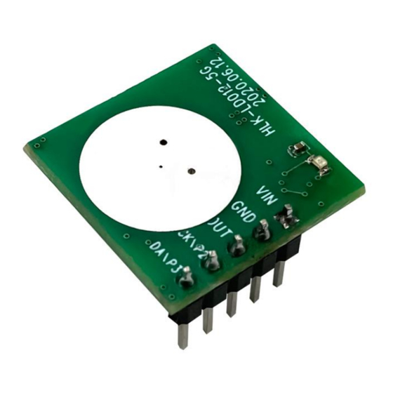
HLK-LD012-5G User Manual The module reserves 5 pin holes, with a total of five signal PINs VCC, GND, OUT, P2 and P3. The PIN distance is 2.54mm. If you need to tune the distance and delay time and other parameters, you can hang or pull down P2 and P3. -
Page 5: Electrical Parameters
5. Sensing time and sensing distance adjustment The P2 and P3 pins on the HLK-LD012-5G module are used to select different sensing distances and delay gears; P2 is used to adjust the sensing distance, which can be provided with the 3 resistors (th0, th1, th2) reserved on the module 16 different sensing distance options. -
Page 6: Photosensitive Detection
HLK-LD012-5G User Manual high, the sensing pull-up time is 2 seconds; when P3 is pulled low, the sensing pull-up time is 15 seconds. If there is a new trigger during the inductive output pull-up period, the inductive time will be extended. -
Page 7: Module Power-On Sequence Diagram
HLK-LD012-5G User Manual 7. Module power-on sequence diagram The module has a power-on self-check function, that is, after the module is powered on, the OUT pin first outputs a high level, and then outputs a low level after a delay of 2S, and enters the normal induction mode after a delay of 0.5S. -
Page 8: Precautions
, Objects can be basically detected in this area. HLK-LD012-5G lateral sensing range diagram (unit m) 9. Precautions 1. When installing the antenna, avoid metal shells or components on the front of the antenna to avoid shielding the signal. -
Page 9: 10. Revision History
HLK-LD012-5G User Manual 10. Revision History Revision Release Date Description 2020/07/08 Initial version 2020/08/03 Update electrical parameters Page 7 / 7...
Need help?
Do you have a question about the HLK-LD012-5G and is the answer not in the manual?
Questions and answers