
Summary of Contents for Scanmar International Pelagic Autopilot
- Page 1 Pelagic Autopilot Installation and User Guide Version 10.2.53 January 2020 Scanmar International, Inc. 14138 Washington Avenue San Leandro, CA 94578 Phone 510.215.2010 www.ScanmarInternational.com...
- Page 2 Revisions • Ver 0.5: Added wind mode description of operation. • Ver 0.6: Added Tiller Actuator mounting dimensions. • Ver .91: Enhanced install instructions and photos. • Ver .92: Added instructions for software update. • Ver .93: Corrected software reload instructions. •...
- Page 3 Revisions (continued) Ver .989 Added Monitor windvane slides showing attachment kit. Ver .989d Corrected rudder sensor slide language. Ver .989f Added software upgrade documentation. Ver 989g: Enhanced software upgrade instructions. Added Monitor revised bracket photos and instructions for assembly. Ver 989h: Description of new Monitor windvane actuator attachment kit. Ver 989i: Improved description of parameter adjustments.
- Page 4 Advanced features allow custom tuning for optimum performance whether cruising or on the race course. The Pelagic Autopilot is comprised of three (3) components; the Control Head, Motor Drive Box and actuator. The modular nature of the Pelagic system allows support for many different applications including: •...
-
Page 5: System Features
System Features • Controls most 12 volt steering systems • Adaptive adjustment for sea state to minimize power • Tiller wands & wheel steering systems • Windvane steering control (low power) • No rudder sensor required • Hydraulic actuators • Motor stall detection and power •... - Page 6 The Pelagic System – Tiller, Quadrant, Wheel, or Windvane Pelagic Components in blue Control Head & Wireless Gyro/Compass Remote Enclosure Mount above or below deck NMEA0183 Wind Option Actuator Two wire, Tiller Drive Actuators high current Motor Electronics Enclosure Motor or Hydr.
- Page 7 Typical Tiller Pilot System Layout Tiller Bulgin Pelagic 20’ control cable Deck Controller with twist lock Outlet Typically Installed Above deck 5’ (1.5m) connectors 2 wire cable Pelagic Motor Customer supplied wiring to Battery Drive Deck connector 1m max Typically Installed Below deck...
- Page 8 Tiller Wand Installation on J92 “Rag Time”...
- Page 9 The Pelagic is Capable of Driving Hydraulics and a Variety of Linear Motors for Tiller or Quadrant Testing of various actuators...
- Page 10 System Components for Tiller Steering...
-
Page 11: The System Controller
The System Controller Provides the user interface for operation of the autopilot. Connects to motor drive box via the data cable. • IP-67 rated enclosure for above deck installation • Contains 9 attitude sensors and compass implementation • White: Standby / Autopilot Mode •... - Page 12 The Motor Drive Box Provides electrical connections for operation of the autopilot. Connects to the Controller via the data cable. • Installed below deck • Inline fuse • Connections to actuator or a below decks systems motor (depending on configuration) •...
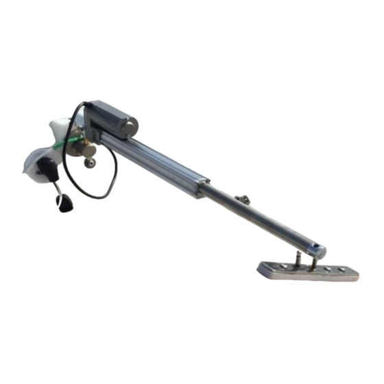
- Page 13 The Linear Actuator • Ruggedized construction • Attaches to tiller 18” (457mm) forward of rudder axis • Deck mount 24 7/16” (621mm) from tiller • Extensions available • Tiller pin = 1/4” stainless • Fixed pin = 0.375” into brass socket •...
- Page 14 The Actuator Mounting Bracket Is Reversible and Rotatable 90° Allows rotation of motor position, up or down Articulates in one dimension to allow tiller motion...
- Page 15 Water Resistant Wireless Remote • See Summary of RF Remote Operation for detailed instructions • Buttons Sealed with Polymer Panel under Keys • Easy Battery Replacement Port 2° Starboard 2° Push A+B simultaneously To engage or disengage Moves rudder Autopilot steering 10°...
- Page 16 Autopilot System Components for Windvane Steering Actuator shown is for windvane control.
- Page 17 Small Linear Actuator for Windvane Steering • Connects to the windvane • Clamps to the 3” tube and the 1” wind paddle tube. • Ball and socket joints retain actuator at both ends. • Ball and socket joints have small retaining springs on outside that swing out to remove or lock the connections.
- Page 18 Installation Procedure For Above Deck Tiller System...
- Page 19 Typical Tiller System Layout Tiller Bulgin Pelagic 20’ control cable Deck Controller with twist lock Outlet Typically installed 5’ (1.5m) connectors above deck Stern or Bow Facing 2 – wire cable Pelagic Motor Customer supplied wiring to Battery Drive deck connector 2m max length Typically installed Below decks...
- Page 20 Material Required for Tiller Installation • Two (2) #8 mounting screws or nuts/bolts for mounting the Motor Drive box • Two (2) #8 mounting screws or nuts/bolts for mounting the Control head • Wire, #16 gauge or larger to connect from the Motor Drive box •...
- Page 21 Electrical Connections For Tiller Steered or Windvane Systems • Power should come from a breaker/fuse panel • A 10amp inline fuse is provided • Maximum current is 15 amps • A 20’ control cable (provided) connects the Control Head with the Motor Drive Box.
- Page 22 Installation for Above Deck Tiller • Prior to beginning the installation, spend a few minutes to determine suitable locations for the major components of the Pelagic system. Consider the following when planning the installation: • Keep the Control box a minimum of 6” away from metal objects, including wires carrying charge loads and the deck compass •...
- Page 23 Installation for Above Deck Tiller • Turn power off to the wires from the vessel switch panel that will connect to the autopilot power. • Connect the large red wire coming from the motor drive box to +12 volts. • Connect the large black wire coming from the motor drive box to ground.
- Page 24 • Refer to System Operation for operational guidelines • The Pelagic Autopilot is calibrated at the factory and unless the boat has a strong magnetic field, it’s not necessary to recalibrate. This can be determined during the on-water testing described below.
- Page 25 Drive Box Connections Standard Tiller Installation Bundled wires not used except for Wind Steering Connector for cable to Control Head 10 amp fuse for standard tiller, 20 amp for below decks systems -Black to ground +Yellow to actuator plug -Green to actuator deck plug +12V RED to power source on panel...
- Page 26 Deck Connections Mount the 3-pin deck socket within 4’ of the actuator mounting bracket • You will need to provide screws or nuts/bolts • Thread one of the mounting screws through the dust cap provided Connect yellow and green wires from the Drive Box to the back of the deck socket (see below) •...
- Page 27 The Bulgin Dust Cap/Moisture Cover Serves as a tool to open up the 3 pin plug attached to the tiller actuator This end is a tool that unscrews a retaining ring within the male plug on the cable. The plug, when viewing the pins, has a threaded retaining ring that can be unscrewed with the dust cap.
- Page 28 Installation Procedure For Below Deck Systems...
- Page 29 Material Required for Below Deck Installation • Two (2) #8 mounting screws or nuts/bolts for mounting the Motor Drive • Two (2) #8 mounting screws or nuts/bolts for mounting the Control head • Wire, #16 gauge or larger to connect from the Motor Drive box to: •...
- Page 30 Installation for Below Deck Systems • Prior to beginning the installation, spend a few minutes to determine suitable locations for the major components of the Pelagic system. Consider the following when planning the installation: • Keep the Control box a minimum of 6” away from metal objects, including wires carrying charge loads and the deck compass •...
- Page 31 Drive Box Connections Below Decks System Installation Clutch Yellow + Clutch Black - Inline 20/25amp Fuse NMEA (for wind data) Green #16 Wires: Black +12 V RED - GND BLK Rudder Sensor Connections MOTOR +YELLOW Orange MOTOR - GREEN Black Note: Any of the small black wires can be used for Clutch, NMEA or Rudder Sensor connections...
- Page 32 Electrical Connections for Below Deck Systems Connecting the Motor Drive and Control Head • Turn power off to the wires on the vessel’s switch panel that will connect to the autopilot power. • Connect the large red wire coming from the motor drive box to +12 volts. •...
- Page 33 Electrical Connections for Below Deck Systems Connecting the Motor Drive to the Below Deck RAM or Pump • Turn off the power to the system. • Connect the large YELLOW wire to the pump motor’s large RED wire, and the large GREEN wire to the pump motor’s large BLACK wire. If the actuator is mounted on the port side these must be reversed.
- Page 34 Connecting the Below Deck Clutch • Turn off the power to the system. • The linear motor will have two, small diameter wires, typically labeled “clutch”, “bypass”, “coil”, or “magnetic clutch”. • Connect one of these two wires to the small YELLOW wire and the other to one of the three small BLACK wires coming from the motor drive box.
- Page 35 Connecting the Rudder Sensor • The small RED, ORANGE, and one small BLACK wire coming from the motor drive box are the rudder sensor inputs. • ORANGE senses the rudder position and the small RED and BLACK wires power the sensor. •...
- Page 36 Rudder Sensor Connections Use a resistive sensor only A rudder sensor is an important component of your below decks autopilot. The Pelagic requires that a resistive type sensor be used. The Raymarine M81105 one example of a resistive unit that can be used and the wiring diagram for that model is shown below. If your sensor is different, you can use a Digital Voltmeter (DVM) to determine how to connect to the Pelagic wires to the sensor.
- Page 37 Rudder Sensor Limit Setting Push and hold STAR and AUTO during power up boot HOLD AUTO 3 POWER – hold STAR and Standby Standby SEC TO EXIT AND Rudder AUTO while in boot process CAPTURE Manually move the tiller, or button Move Move Starboard...
- Page 38 • Refer to System Operation for operational guidelines • The Pelagic Autopilot is calibrated at the factory and unless the boat has a strong magnetic field, it’s not necessary to recalibrate. This can be determined during the on-water testing described below.
- Page 39 Installation Procedure For Windvanes...
- Page 40 Installing with a Windvane Except for how the actuator is mounted, the installation of the Pelagic autopilot for windvanes is similar to the standard tiller system. The type and mounting location of the actuator varies depending on the windvane being used. For example: •...
- Page 41 Setting Parameters for Windvane Steering The Pelagic Autopilot is preconfigured from the factory to perform well on most boats in a variety of conditions. If ordered for windvane steering, your Pelagic Autopilot is preconfigured from the factory with the following settings:...
- Page 42 Installing the Actuator on a Monitor Windvane The Pelagic system for the Monitor windvane is comprised of three (3) major components: • The Controller • Motor drive box • Actuator mount including: • Small actuator • Polarity (ships with polarity set for starboard mounting) •...
- Page 43 Installed Monitor Brackets Quick pin and ball joint allows quick release Frame Bracket Installed Pinion Bracket Ball Joint Connection...
- Page 44 Remove the airvane from the Monitor Attach the actuator to its base bracket and connect the ball joint at the end of the actuator RAM to the receiver on the Monitor gear set Power on the Pelagic Autopilot Remove the airvane from the Monitor...
-
Page 45: System Operation
System Operation... - Page 46 Operation BUTTON Auto Port Star Auto Port Star Port Star -push -push -push -3sec -3sec -3sec -6sec -6sec hold hold hold hold hold MODE Standby mode Go to Rudder to Rudder to Wind Mode Go to GAIN ----------------- DIM Display Reserved (red LED slow Auto Mode...
- Page 47 Quick Reference Guide Hold AUTO 3 sec & Hold 3 sec & Standby Release Release Push AUTO Push AUTO Wind Mode Gain Adj Increase Hold AUTO 3 sec & Decrease Auto Release TACK - TACK Push Push Hold & Hold & + 2°...
- Page 48 Controller Front Panel Operation Increase Decrease =1 sec push GAIN to Standby Red Light Pattern Standby Standby POWER UP – START HERE Compass Wind Tack to Auto Tack to Auto Port Wind Starboard Compass Button Colors Turn PORT Turn STAR 2°...
- Page 49 RF Remote Operation Summary Standby Push A+B Auto Push A+B All button functions are identical to front panel operation Push A Push B Star: Turn +2° Port: Turn -2° HOLD for Tack HOLD for Tack...
- Page 50 Summary of RF Remote Operation BUTTON Push A & B Port Star Hold Port Star Port Star RF Remote A & B push (A) push (B) 3 sec 3sec 3sec 6sec 6sec PORT & STAR Hold Hold Hold Hold Simultaneously MODE Standby Go To Auto...
- Page 51 Gain Adjustment The gain is displayed whenever the Pelagic is placed into Auto mode, with the gain setting equal to the number of green LEDs illuminated. These can be shown in both solid and flashing states. For example, a gain of 3 is displayed as 3 solid green lights, whereas a gain of 3-1/2 is displayed as 3 solids and a flashing green.
- Page 52 GAIN ADJUSTMENT 9 levels 0 – 4.5 in half steps RED LED Flashes Standby Once per Second In Standby Hold Hold PORT 3 sec to enter. A brief push of AUTO PORT AUTO saves new setting and exits to STANDBY. 3 secs 1 sec to exit...
- Page 53 Connecting Wind Steer Feature (apparent wind angle) The Pelagic can adjust steering angle based on the apparent wind direction To enable the Wind Steer feature, the Pelagic needs to receive wind input directly from the NMEA 0183 network or from an NMEA 2000 network via a gateway In NMEA terms, the Pelagic will be looking for the sentence “xxVWR”...
- Page 54 Notes on Steering with the Wind Steer Feature If wind data is not present on the NMEA network the Pelagic will not go into Wind Mode. Lack of wind mode data can be the result of several things including: NMEA network is not creating/sending “xxVWR” sentences •...
- Page 55 WIND STEER MODE (apparent wind angle) Red LED Blinks short-long -long Standby AUTO hold 3 secs AUTO hold 3 to enter secs to exit Standby in Wind WIND MODE: The AP adjusts the steering angle Mode based on the apparent wind angle. The relative wind angle is received from the NMEA-0183 data bus.
- Page 56 The 4 GREEN lights will flash 3 times during the transition • Once orientation setting is correct, push AUTO for approximately 3 seconds to store setting and return to standby mode • Recalibrate the system before using the Pelagic autopilot...
- Page 57 ORIENTATION SELECTION (Orienting the control head) Hold PORT button during boot process Red LED flashes Now Select Your Three Long Orientation by Hold PORT Power On pulses when Pushing PORT or through bootup in Orientation STAR mode Front Panel Facing Front Panel Facing Front Panel Facing Front Panel Facing Aft...
-
Page 58: Calibrating The Compass
Calibrating the Compass • Compass Linearization – Swinging the Compass • Initial calibration of the Pelagic is performed at the factory and it is typically not necessary to recalibrate the unit. • However, if there is magnetic interference from foreign objects on the boat, then it will be necessary to recalibrate on the vessel. - Page 59 Compass Calibration Linearization – Swinging the Compass NOTE: If calibration process is not successful, the right GREEN LED will turn solid and the port RED LED Red LED flashes this sequence will flash rapidly the next time the system reboots, indicating a poor calibration.
- Page 60 Compass Linearization Lights shown as each calibration point is entered. Hold each heading for approximately 10 secs before pushing AUTO to Hold AUTO 3 seconds until boot move on process begins to store settings Turn to starboard in 45° increments. At each increment, push AUTO 1 sec.
-
Page 61: Advanced Features
Advanced Features The Pelagic Autopilot is preconfigured from the factory to perform well on most boats in a variety of conditions. Nevertheless, there may be situations where additional tuning is required, particularly with high performance boats. The Pelagic system can be enhanced to accommodate the demands of high performance boats through a series of advanced features called Dynamic Parameters. - Page 62 Dynamic Parameter Adjustment – Enable at Power Up (when in this mode the GAIN is preset to 3) • Power up and hold the AUTO button until boot process completes. • The RED led will flash a long-short, long-short pattern. •...
- Page 63 Dynamics Parameter Settings • GAIN set to 3 • Full keel boats (starting settings): • Low Speed Course Correction (KISub) = 0 • Course Correction (KI) = 1.5 • Yaw Suppression (KP ) • Yaw Damping (KDI) • Yaw Acceleration Rate (KYDD) = 3.5 •...
- Page 64 Adjustment of Dynamic Parameters Light OFF: Reserved for future use Light 1: Course correction Light 2: Yaw suppression Light 3: Yaw damping (similar to Continuous course correction but uses Rate Gyro) Light 4: Yaw rate of change damping adjustment (helps with gusting winds/seas) (KYDD) Green lights from left to right...
- Page 65 Dynamic Parameter Selection Or return to factory settings Select a Hold AUTO Red LED flashes Power On Parameter using until boot Long-Short when GRN/RED completes in Calibration Course High Speed Low Speed Course Yaw Oversteer Yaw Suppression Correction Course Correct Correction Damping Gyro...
- Page 66 Parameter Adjustment From ParameterSelection WHEN IN THIS MODE THE AP IS IN CONTROL. Adjust Selected Red LED flashes ADJUST the SELECTED SETTING: FAST when Parameter for Each has 9 levels Best Performance in ADJUST mode Odd levels flash one green LED Level 0 Level 1 Level 2...
- Page 67 Optimization Adjustment Method Listed in order of green LED, left to right Parameter Adjust settings in mild conditions, flat water. Selection Low speed course correction (DONT CHANGE) Course correction: (3rd) if the boat reacts too slowly in light conditions try increasing. If it starts getting snake-ie reduce or go up 1 step Yaw Rate Suppression: (1st Start...
-
Page 68: Parameter Adjustment
Parameter Adjustment (when in this mode the GAIN is preset to 3) • Setting Adjustment • 5 settings exist for calibration • Red flashes fast when in AP • They are accessed at power up mode. by entering Calibration mode. •... - Page 69 Dynamics Parameter Adjustment The 4 green LED’s display the parameter value. 0 = no green LEDs lit. 1/2 = LED 1 flashing 1= LED 1 solid 1 1/2 = LED 2 flashing 2 = LED 2 solid 2 1/2 = LED 3 flashing 3 = LED 3 solid 3 1/2 = LED 4 flashing 4 = LED 4 Solid...
- Page 70 Typical Parameter Settings Parameter Wind Vane/Full Keel Fin Keel/Spade Rudder Low speed course correction O O O O O O O O Course Correction 1.5 = @ X O O @ @ O O Yaw Rate Suppression 2 .5 = @ @ X O 3.5= @ @ @ X...
-
Page 71: Technical Notes
Technical Notes... - Page 72 ActiSense NGW-1 Connections for NMEA 2000 to NMEA 0183...
- Page 73 ActiSense Wiring Blue – small Black NGW-1 Pelagic AP White – small Green...
-
Page 74: Unit Dimensions
Unit Dimensions... - Page 75 Control Head Dimensions Units Shipped after May 2017 Two mounting holes are Cable exits thru a 25 mm (1”) Beneath access tabs on Diameter cable gland. Mounting The case face. Must include a hole to receive.
-
Page 76: Motor Drive Box
Motor Drive Box Note box dimension does not show mounting flanges... - Page 77 Tiller Actuator Dimensions .25” (6.3mm) hole End bracket may appear different than actual, dimensions are accurate. Swivel 2.94” (74.8mm) Yoke Stroke 10” (250mm) .5”(12mm) .375” (9.5mm) Diameter Length nominally 1”(25.4mm) – adjustable. 24 7/16.” (621.mm)
- Page 78 Tiller Actuator Mounting Spec - Deck/Rail pin diameter 0.375” (9.53 mm) - Rudder axis to mounting pin Deck Rail Pin 18” (457mm) - Tiller mounted pin diameter 0.25” (6.35mm) Rudder Tiller Mounting bracket may vary 18” (457.2mm) Axis Pin (1/4”) With date of manufacturing.
-
Page 79: Remote Controls
Remote Controls... - Page 80 Remote Controls Learning remote. Available September 2019 Original remote. Shipped prior to September 2019...
- Page 81 Actuator Connector as Shipped for Starboard Mounted Actuator Reverse green and yellow for port side actuator mounting Female Deck Flange Connector front view. Internal color code. Reverse for Port mounting of actuator Male Cable Connector Attached to Tiller Actuator From Motor Drive box Internal color code Front view From Motor Drive box...
- Page 82 Deck Connector When mounting the actuator on the port side, the green and yellow wires are reversed as shown...
- Page 83 Bulgin Male Plug Assembly This cap also is used To screw open the Plug assembly...
- Page 84 Windvane Kits...
- Page 85 Monitor Wind Vane installation on “Owl”, Pacific Seacraft 37. Shown testing a prototype revision of the wind vane steering.
- Page 86 Windpilot Attachment Kit 2 in (50mm) down tube bracket 6mm ball joint 6.5 mm spacer • 12 Volt linear motor push rod, 75 mm span. • 2 – 6mm quick release ball joints • 50mm Down tube attachment brackets M6x1-75mm length •...
- Page 87 Windpilot Pacific Actuator and Parts To Universal Joint Down Tube Clamp. Adjust for Alignment...
- Page 88 SailOMat attachment kit & photo of attach points 6 mm allen key required for 6 mm cap screws in 3” bracket...
- Page 89 Pelagic Software Updates Upgrading System Software...
-
Page 90: Upgrade Requirements
Upgrade Requirements • A Windows PC running Windows 7 or later. • Or An Apple PC running a recent version of IOS. • A mini-B USB cable that fits into the computer USB port. • The mini-B side connects to the Pelagic control unit Mini B connector •... - Page 91 Receiving Software via Email • Create a new folder, “PelagicSW”, or pick a name. • Download, or move, the ZIP file into the directory created. • Open the folder containing the ZIP file with windows explorer. • Right-click on the ZIP file and select “Extract All”. This will decompress the files into a new folder.
- Page 92 Loading the New Software • Power off and remove the Pelagic control unit. • Using a small-head Philips screw driver, open the autopilot control head by removing 6 screws on the back. • Note the original model has 4 screws on the face. Remove six (6) screws •...
- Page 93 The Teensy Loader for Windows PC Click on Verbose Mode under the Help button This is the Teensy loader window. It will to view status of the download. If no errors appear when you run the teensy.exe file appear it has loaded successfully. Auto Button Program Load...
- Page 94 Loading New Software (continued) • Make sure the small AUTO button on the TEENSY loader is Mini B - USB GREEN. Click on it to change the state. If this does not happen go to the file button on the TEENSY screen and click connector on “Open Hex file”.
- Page 95 Control Head Models – Access to the USB connector. Current Model: USB Connector is Original model: The USB connector is exposed by removing 6 screws on exposed by removing 4 screws on the the back of the control head. front panel and then the circuit board by removing the 3 screws holding it in place.
-
Page 96: Troubleshooting
Troubleshooting... - Page 97 Trouble Shooting Symptom Solution • • System reboots intermittently Check wiring for loose connections, reseat fuse(s) • • After system start up, the panel displays a solid This indicates a bad calibration. Recalibrate. Green LED for about 8 seconds, then goes away •...
- Page 98 Requesting Tech Support • When emailing or calling for technical support please provide the following information: • Name • Type, length of boat • Type of Pelagic system installed (standard tiller, below deck etc. • Serial number of your system components •...
Need help?
Do you have a question about the Pelagic Autopilot and is the answer not in the manual?
Questions and answers