Table of Contents
Advertisement
Quick Links
Advertisement
Table of Contents

Summary of Contents for SONOVE M2-M
- Page 1 OPERATING MANUAL MARINE MONITOR M2-M M2-M_Operating_Manual_2.0.0...
- Page 2 © 2020 Sonove GmbH. All rights reserved. This document is proprietary and the property of Sonove GmbH. Reproduction, publication or representation of its contents in whole or in part is expressly forbidden. All brand or product names are trademarks or registered trademarks of their respective holders.
-
Page 3: Table Of Contents
M2-M Operating Manual | Table of Contents TABLE OF CONTENTS SAFETY NOTES ..............................I ............................... I AFETY YMBOLS ................................I ROPER ............................. I PERATING ERSONNEL PREFACE ................................. III ............................III EQUIRED KNOWLEDGE ................................... III COPE ............................III DITIONS AND EVISIONS ............................ - Page 4 M2-M Operating Manual | Table of Contents 4.4.3 Sub Menu – Position Settings ......................29 4.4.4 Sub Menu – OSD Settings ....................... 31 4.4.5 Sub Menu – Setup .......................... 32 ANNEX ................................37 ............................. 39 ELATED OCUMENTS M2-M_Operating_Manual_2.0.0...
-
Page 5: Safety Notes
M2-M Operating Manual | Safety Notes SAFETY NOTES This manual contains important information which must be observed to ensure your own personal safety, as well as the safety of the product and your equipment. The following safety notes must be read carefully to prevent injury to people and damage to property. -
Page 7: Preface
M2-M Operating Manual | Preface PREFACE Thank you for purchasing a Sonove Monitor. Please notice, that the operating instructions are an integral part of the product and contain important information for operation and service. The operating instructions are written for all persons, who assemble, install, start-up, operate and service this product. -
Page 8: Illustrations
To ensure safe operation of the product and to achieve the specified product characteristics and performance requirements you must comply with the information contained in this manual. Sonove GmbH does not assume liability for injury to persons or damage to equipment or property resulting from non-observance of the operating and safety instructions. -
Page 9: Conventions
M2-M Operating Manual | Preface CONVENTIONS To clearly distinguish the different types of information the following conventions are used in this manual: Important elements are characterized bold to find them quickly. Cursive characterized words indicate examples. Code examples, folder names, direct inputs, function-keys, keys of the keyboard as well as buttons of the program and others are characterized in non-proportional font. -
Page 11: Product Overview
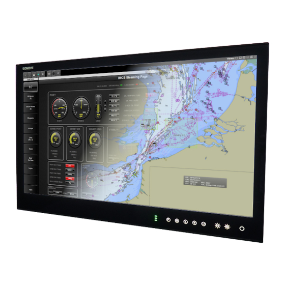
The M2 monitors are part of our completely new designed M2 series, developed to satisfy the demands of today’s marine craft and marine applications. The Sonove M2 products combine elegant design with robust construction and highest performance. They are designed for nearly all types of marine application and provide high reliability and long-term availability. -
Page 12: Mounting
M2-M Operating Manual | Product Overview 1.3 MOUNTING The monitors of the M2 series support the following mounting options: Flush mounting Desktop, wall, ceiling mounting INFORMATION Please notice, that special mounting brackets/a special console mounting kit will be required! Accessories (e.g. brackets, screws) are not included in the delivery scope of the monitor. They can be ordered on our website. -
Page 13: Scope Of Supply
M2-M Operating Manual | Product Overview 1.5 SCOPE OF SUPPLY The following components are included in the delivery scope of the monitors: 1x Monitor 1x Grounding Kit 1x Power AC Cable, 2.50 m (only AC systems) 1x DC Plug (only DC systems) 1x USB Touch Cable, 3.00 m... -
Page 14: Unpacking
· Please observe local regulations for product disposal and recycling. For more information, please contact the responsible authority in your municipality or city. · Sonove generally recommends that customers dispose of the product in an environmentally sound manner. Potential methods include reuse of products or product parts and recycling of products, components and/or materials. -
Page 15: Cleaning
M2-M Operating Manual | Product Overview WASTE ELECTRICAL AND ELECTRONIC EQUIPMENT DIRECTIVE (WEEE) In the European Union, this label indicates that this product should not be disposed of with household waste. It shouldbe deposited at an appropriate facility to enable recovery and recycling. For detailed information about return and recycling of this product please contact the responsible authority in your municipality/city or your sales representative. -
Page 17: Safety Instructions
M2-M Operating Manual | Safety Instructions 2 SAFETY INSTRUCTIONS The following safety instructions and warnings on the product must be read carefully to prevent injury to people and damage to property. WARNING: Assure that the personnel responsible for installation and operation of this product has... - Page 18 M2-M Operating Manual | Safety Instructions WARNING: The product must be grounded in any case! Non-observance may cause electric shock or hazard, fire, product damage and/or severe or fatal injuries! WARNING: Safe power connection must be ensured! Unsafe power connection may cause electric shock or hazard, fire, product damage and/or severe or fatal injuries! ·...
- Page 19 M2-M Operating Manual | Safety Instructions WARNING: The product is not certified as medical electrical equipment, and is not intended for use in close proximity to patients or oxygen rich environments. Non-compliance may cause electric shock or hazard, fire, product damage and/or severe or fatal injuries! WARNING: High frequency radiation (e.g.
-
Page 21: Mounting And Connecting
M2-M Operating Manual | Mounting and Connecting 3 MOUNTING AND CONNECTING Before monitor is mounted/ connected the following safety instructions/ information must be observed: WARNING: Ensure instruction, qualification and authorization of executing personnel! Non- observance of this information may cause electric shock or hazard, fire, product damage and/or severe or fatal injuries! ·... - Page 22 M2-M Operating Manual | Mounting and Connecting WARNING: Ensure adequate cooling of product! Non-observance of this information may cause electric shock or hazard, fire, product damage and/or severe or fatal injuries! · Check for adequate air circulation around product (refer to adjacend Figure)! ·...
- Page 23 M2-M Operating Manual | Mounting and Connecting INFORMATION Please notice, that accessories (e.g. brackets, screws) are not included in the delivery scope of the monitor. They can be ordered on our website. INFORMATION Please notice, that claims for transportation damage can only be recognized if they are claimed before initial operation of the product! M2-M_Operating_Manual_2.0.0...
-
Page 24: Mounting
M2-M Operating Manual | Mounting and Connecting 3.1 MOUNTING There are several options for mounting of the monitor. The product can be flush mounted into a plane surface or console as well as in desktop, wall or ceiling position. WARNING: Ensure correct orientation of the monitor! Non-observance of this information may cause product damage and/or severe or fatal injuries! ·... -
Page 25: Connecting
M2-M Operating Manual | Mounting and Connecting 3.2 CONNECTING The interfaces of the monitor are located on the back of the product. The following graphic shows an example of a M2-M-24 slot bracket: Figure 7: Slot Bracket M2-M-24 DCAC INFORMATION Please notice that the interfaces of the monitor depend on the product type (article no.) and may therefore... -
Page 26: Dvi-D
M2-M Operating Manual | Mounting and Connecting INFORMATION The type of supported power supply depends on the configuration of the monitor. INFORMATION The monitor is connected to AC voltage by a standard AC power cable. For AC systems a AC power cable is included in the delivery scope. -
Page 27: Serial Interface (Rs 232)
M2-M Operating Manual | Mounting and Connecting 3.2.3 SERIAL INTERFACE (RS 232) The monitor is equipped with a RS 232 D-SUB socket. The following table lists the port assignments: Pin Assignment Signal/ Description Signal/ Description Pin 1 Not connected Pin 6... -
Page 28: Source Select (Smp-03V-Bc)
M2-M Operating Manual | Mounting and Connecting INFORMATION Please notice, that a capacitive touch (CT) is an optional feature of the M2-M-24 monitors! The following information only applies if the product has a capacitive touch! The touch display must be connected to an USB port of the computer! For systems that are equipped with capacitive touch, the correct USB cable is included in the delivery scope. -
Page 29: External Potentiometer
M2-M Operating Manual | Mounting and Connecting 3.2.10 EXTERNAL POTENTIOMETER For brightness control an external potentiometer can be connected to the monitor. In order to be automatically recognized, the electrical resistance of the potentiometer must have a certain value. Figure 18: Connecting diagram for potentiometers with an electrical resistance of 470 kΩ... -
Page 31: Operating
M2-M Operating Manual | Operating 4 OPERATING The following instructions assume the successful installation and commissioning of the product, as well as comprehensive knowledge of the relevant documentation and safety notes. The following steps must be observed before operating the monitor:... -
Page 32: Osd Control Pad
M2-M Operating Manual | Operating 4.2 OSD CONTROL PAD The different parameters of the OSD can be adjusted via an external interface. Use the OSD Control Pad to open/close the OSD Menu and to navigate through the menu structure. The OSD Control Pad is located at the... -
Page 33: Osd Menu
M2-M Operating Manual | Operating 4.4 OSD MENU The OSD allows fine tuning of various functional parameters. The figures below give an overview of the different OSD menus and submenus, which are described in detail in the following subsections. INFORMATION... - Page 34 M2-M Operating Manual | Operating Figure 25: Submenus of OSD Menu “OSD Settings” Figure 26: Submenus of OSD Menu “Setup” M2-M_Operating_Manual_2.0.0...
-
Page 35: Sub Menu - Image Settings
M2-M Operating Manual | Operating 4.4.1 SUB MENU – IMAGE SETTINGS INFORMATION Please notice that the range of possible configurations within the OSD Menu “Image Settings” depends on the input type as well as the version of the firmware and may therefore differ from the following figures and descriptions. - Page 36 M2-M Operating Manual | Operating Advanced Image Settings | Advanced The advanced menu opens in two ways, according to input type. > Color Image Settings | Advanced | Color Opens the dialog for color settings. >> Color Temp Image Settings | Advanced | Color | Color Temp Allows selection of different color temperature schemes.
- Page 37 M2-M Operating Manual | Operating >> CCS Mode Image Settings | Advanced | Noise Reduction | CCS Mode Changes Cross-Color Suppression between off/adaptive/normal. Adjust for best image. High setting may cause loss of detail, adjust for best image. >> Dynamic NR Mode Image Settings | Advanced | Noise Reduction | Dynamic NR Mode Changes Dynamic Noise Reduction between low/medium/high/off/adaptive.
-
Page 38: Sub Menu - Display Settings
M2-M Operating Manual | Operating 4.4.2 SUB MENU – DISPLAY SETTINGS INFORMATION Please notice that the range of possible configurations within the OSD Menu “Display Settings” depends on the input type as well as the version of the firmware and may therefore differ from the following figures and descriptions. -
Page 39: Sub Menu - Position Settings
M2-M Operating Manual | Operating Tiling Display Settings | Tiling The tiling function (for video wall applications) can be used with all input types. > Horizontal Total Display Settings | Tiling | Horizontal Total Defines the total horizontal number of displays. - Page 40 M2-M Operating Manual | Operating Width Position Settings | Width (Only for video mode of HDMI, S-Video, composite and component inputs) Adjusts total width of the image by stretching or shrinking. Height Position Settings | Height (Only for video mode of HDMI, S-Video, composite and component inputs) Adjusts total height of the image by stretching or shrinking.
-
Page 41: Sub Menu - Osd Settings
M2-M Operating Manual | Operating 720p Position Settings | 720p (Only for graphics mode of HDMI) Select Video or Graphics optimization for 720p content. INFORMATION Please notice, that selection of Video optimization entails optimzation of internal algorithms for videos (moving content), whereas selection of Graphics optimization entails optimization of internal algorithms for graphic input (static content e.g. -
Page 42: Sub Menu - Setup
M2-M Operating Manual | Operating OSD Zoom OSD Settings | OSD Zoom Changes OSD size. Keypad Layout OSD Settings | Keypad Layout Change between 6-Button or 4-Button OSD-Keypad. Advanced OSD Settings | Advanced This function can be used to set the presentation of the window. - Page 43 M2-M Operating Manual | Operating Show Menu Of Setup | Show Menu Of Changes the menu between Main image and PIP if the PIP mode is on. Input Search Setup | Input Search Toggles input search on/off. Advanced Setup | Advanced This menu can be used to adjust various engineering setups.
- Page 44 M2-M Operating Manual | Operating > Dimming Mode Setup | Advanced | Dimming Mode This function can be used to set the diming mode. The following configuration options are possible: Setting CB/ROSD Comment Optimized Calibrated 5 Level Min, 1%, 20%, 60%, 80%, Max Linear 0 ...
- Page 45 M2-M Operating Manual | Operating PIP Input Setup | PIP Input Shows the detected input mode (resolution and frame rate) of the PIP input channel. Firmware Version Setup | Firmware Version Shows the version of the firmware. OSD Version Setup | OSD Version Shows the version of the OSD.
-
Page 47: Annex
ANNEX M2-M_Operating_Manual_2.0.0... -
Page 49: Related Documents
Operating Manual M2-M-24 | Annex RELATED DOCUMENTS The information presented in this manual is complemented and specified by other documents which refer to your product type or provide general information. WARNING: Personnel that is responsible for installation and operation must have carefully read and understood the operating instructions and safety notes as well as the related documents that refer to the specific product type. - Page 50 Sonove GmbH Hindelanger Straße 33 87527 Sonthofen Germany Phone: +49 8321 67466 200 Fax: +49 8321 67466 199 Mail: marine@sonove.com Web: www.sonove.com M2-M_Operating_Manual_2.0.0...
Need help?
Do you have a question about the M2-M and is the answer not in the manual?
Questions and answers