Table of Contents
Advertisement
Advertisement
Table of Contents

Subscribe to Our Youtube Channel
Related Manuals for Topcon TRC-50EX


Summary of Contents for Topcon TRC-50EX
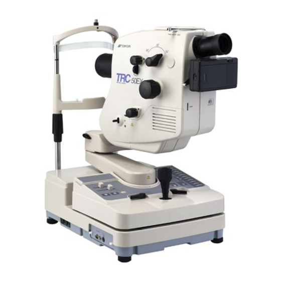
- Page 1 35˚ 20˚ 50˚ 50EX RETINAL CAMERA INSTRUCTION MANUAL RETINAL CAMERA...
-
Page 2: Introduction
INTRODUCTION Thank you for your purchasing the TOPCON TRC-50EX Retinal Camera. THIS INSTRUMENT HAS THE FOLLOWING FEATURES: • This instrument assists the oser in obtaining pictures of exceptional and stable quality. • The instrument is easier to use and operate than previous models. -
Page 3: Display For Safe Use
DISPLAY FOR SAFE USE In order to encourage the safe use of products and prevent any danger to the operator and others or damage to properties, important warnings are put on the products and inserted in the instruction manuals. We suggest that everyone understand the meaning of the following displays and icons before reading “Safety Cautions”... -
Page 4: Safety Cautions
SAFETY CAUTIONS This instruction manual specifies safety cautions necessary to prevent accidents. Always observe these precautions and use the instrument correctly. WARNING Icons Prevention item Page • Do not disassemble, remodel or repair this instrument. Such actions may cause electric shock. If repairing is necessary, be sure to contact your authorized dealer and ask for repair services. - Page 5 CAUTION Icons Prevention Item Page • Ensure that the illumination lamp is not brighter than necessary. Excessive intensity may result in patient discomfort. • Ensure that light brighter than necessary is not used for photography. Excessive intensity may result in patient discomfort. •...
- Page 6 CAUTION Icons Prevention Item Page • Before transporting, set the tilting unit down and lock the tilt brake lever so that the base's up-and-down movement may be at the − minimum. If transporting without locking the movement, the instrument loses its balance and you may be injured.
-
Page 7: Usage And Maintenance
• TOPCON shall not take any responsibility for damage derived from the inability to use this equipment, such as a loss of business profit and suspension of business. -
Page 8: Warning Indications And Positions
WARNING INDICATIONS AND POSITIONS To ensure safe usage of this equipment, precaution indications are provided. Abide the following warning instructions. If any of the following labels are missing, please contact us at the address stated on the back cover. CAUTION To avoid potential injury, do not put your •... -
Page 9: Table Of Contents
CONTENTS INTRODUCTION Preparing the patient DISPLAY FOR SAFE USE Flash intensity setting SAFETY CAUTIONS 35mm color photography USAGE AND MAINTENANCE Fluorescein photography ESCAPE CLAUSE OPERATIONS FOR ADDITIONAL WARNING INDICATIONS AND Photography with optional filters POSITIONS Photography using blue filter STRUCTURE AND NOMENCLATURE Stereo photography Main Body Recording patient data by ID mode... -
Page 10: Structure And Nomenclature
STRUCTURE AND NOMENCLATURE Main Body 35˚ 20˚ 50˚ 50EX RETINAL CAMERA 1 Angle changing lever ....50°, 35° or 20° can be selected as an angle of coverage. 2 Diopter compensation knob ..Used to compensate the dioptric power of strong myopia and hyperopia in the patient and also used for ocular anterior photography. - Page 11 C Shutter release button....Xenon lamp flashes upon depressing the shutter release button. D 35 mm camera body locking lever E Mount for 35 mm camera body F Alignment illumination point switch G Lower arm H Upper arm.........Swings up to 30° to the right and left. I Tilting handle ......Swings up to 15°...
-
Page 12: Control Unit
Control Unit N BARRIER switch ..Press the switch to set the barrier filter. Press again to remove the barrier filter. O EXCITER switch ..Press this switch to set the excitation filter. Press again to remove the excitation filter. P TIME switch ... - Page 13 [FA Filter Setting switch ..With this switch set to ON, fluorescein filter is interlocked at the time of photographical operation. Interlocking can be canceled by turning it off. (Photographing is possible using a blue filter.) \ Exposure setting switch ..Set this switch to “1" for manual mode or to ”2" for program mode. ] Data display unit ....Displays data recorded on film (counter, timer, I.D., angle of coverage and left or right eye or error).
-
Page 14: 35Mm Camera
35 mm camera a Back-cover release lever b Rewinding crank c Rewind switch d Film counter e Mount STRUCTURE AND NOMENCLATURE... -
Page 15: Power Supply Unit
Power Supply Unit 35˚ 20˚ 50˚ 50EX 50EX RETINAL CAMERA RETINAL CAMERA f Power switch n Chinrest g Body connection cord o Height level marker: Patient’s eye must be h Base connecting cord aligned with this marking. i Power cord p Head strap j Primary fuse holder q CONTROL terminal: Used for connection... -
Page 16: Accessories
Accessories Quantity Quantity • Accessories case • Hexagonal wrench (large) • Chinrest paper • Hexagonal wrench (small) • Chinrest paper fastening pins • Tilt brake lever • Internal Fixation target • Fuses (Quantity is changed depending (This is an option in some areas.) on the used areas.) •... -
Page 17: Assembly
ASSEMBLY Components 35˚ 20˚ 50˚ 50EX RETINAL CAMERA Description Quantity Casing Main body Main body Power supply unit Power supply unit Dust cover Main body Instruction Manual Main body 35mm camera Power supply unit Fixation target Power supply unit Phillips screwdriver Main body Connector cover set screw Main body... -
Page 18: Assembling Procedure
Assembling procedure When handling the main body and power supply unit, hold them firmly. If dropped or if your hands and fingers are caught between components, they may cause injury. • Do not disassemble, remodel or repair this instrument. Such actions may cause electric shock. If repairing is WARNING necessary, be sure to contact your authorized dealer and ask for repair services. - Page 19 (1) Remove the power supply unit from its storage box and place on a table. • Be careful not to have your fingers pinched. (2) Set the upper arm fixing knob to the dot mark position. (3) Insert the upper arm over the shaft protruding from the lower arm.
-
Page 20: Checking After Assembly
Checking after assembly • Disconnect the power plug from the outlet before measuring the power frequency. CAUTION Electric shocks may otherwise occur. (1) Checking the primary voltage Check that input voltage is within the range of +10% of the rated voltage. For higher input voltage, a constant-voltage power supply 120 V (commercial product) must be used.
Need help?
Do you have a question about the TRC-50EX and is the answer not in the manual?
Questions and answers