
Subscribe to Our Youtube Channel
Related Manuals for Woodward TUG 4

Summary of Contents for Woodward TUG 4
- Page 1 37303A TUG 4 Temperature Monitoring Unit Operation Manual Software Version 1.6xx/2.6xx Manual 37303A...
- Page 2 Provides other helpful information that does not fall under the warning or caution categories. Woodward reserves the right to update any portion of this publication at any time. Information provided by Woodward is believed to be correct and reliable. However, Woodward assumes no responsibility unless otherwise expressly undertaken.
-
Page 3: Table Of Contents
The information in this publication is no longer current, and may not reflect changes or safety issues that have occurred since the publication was originally released. Refer to the TUG 4 Packages manual 37359 for more recent information about the TUG 4 unit. Content 1. - Page 4 Manual 37303A Temperature Monitoring Unit - TUG 4 8. C ....................25 HAPTER ONFIGURATION Password .............................. 25 Measuring Inputs ..........................26 Pt100 Measuring Inputs ......................27 0/4 to 20 mA Measuring Inputs ....................28 Discrete Inputs............................30 Relay Outputs ............................30 Interfaces (Option Su) ..........................
- Page 5 Figure 4-3: Wiring diagram TUG 412 ............................. 11 Figure 4-4: Wiring diagram TUG 412/Th..........................12 Figure 4-5: Wiring diagram TUG 416 ............................. 13 Figure 4-6: Data coupling TUG 4 ............................14 Figure 5-1: Power supply................................. 15 Figure 5-2: Discrete inputs............................... 15 Figure 5-3: Relay output ................................
-
Page 6: Chapter 1. General Information
TUG 416 16 measuring inputs Please refer to the name plate of your TUG 4 to establish the correct type. Intended Use The control unit must only be operated as described in this manual. The prerequisite for a proper and safe operation of the product is correct transportation, storage, and installation as well as careful operation and maintenance. -
Page 7: Chapter 2. Electrostatic Discharge Awareness
CAUTION To prevent damage to electronic components caused by improper handling, read and observe the pre- cautions in Woodward manual 82715, Guide for Handling and Protection of Electronic Controls, Printed Circuit Boards, and Modules. © Woodward Page 7/55... -
Page 8: Chapter 3. Housing
Manual 37303A Temperature Monitoring Unit - TUG 4 Chapter 3. Housing Dimensions ≡≡≡≡≡≡≡≡≡≡≡≡≡≡≡≡≡≡≡≡≡≡≡≡≡ Front view DIN rail mount option Bottom view Back view with connecting terminals 57 56 2004-10-04 | TUG 4 Dimensions t4ww-4104-ab.skf Figure 3-1: Dimensions TUG 4 Page 8/55... -
Page 9: Chapter 4. Wiring Diagrams
Pt100 input 1 Analog input 1 Ready for operation Wire break Relay 2 Relay 1 0 Vdc 24 Vdc Subject to technical modifications. 2004-09-22 | TUG 4 Wiring Diagram t4ww-0439-ap.skf Figure 4-1: Wiring diagram TUG 404 © Woodward Page 9/55... -
Page 10: Tug 408
Pt100 input 1 Analog input 1 Ready for operation Wire break Relay 2 Relay 1 0 Vdc 24 Vdc Subject to technical modifications. 2004-09-22 | TUG 4 Wiring Diagram t4ww-0439-ap.skf Figure 4-2: Wiring diagram TUG 408 Page 10/55 © Woodward... -
Page 11: Tug 412
Relay 2 Pt100 input 11 Analog input 11 Relay 1 Pt100 input 12 Analog input 12 0 Vdc 24 Vdc Subject to technical modifications. 2004-09-22 | TUG 4 Wiring Diagram t4ww-0439-ap.skf Figure 4-3: Wiring diagram TUG 412 © Woodward Page 11/55... -
Page 12: Tug 412/Th
+20 mA Analog input 11 0 mA Relay 1 +20 mA Analog input 12 0 mA 0 Vdc 24 Vdc Subject to technical modifications. 2004-09-22 | TUG 4 Wiring Diagram t4ww-0439-ap.skf Figure 4-4: Wiring diagram TUG 412/Th Page 12/55 © Woodward... -
Page 13: Tug 416
Relay 2 Pt100 input 15 Analog input 15 Relay 1 Pt100 input 16 Analog input 16 0 Vdc 24 Vdc Subject to technical modifications. 2004-09-22 | TUG 4 Wiring Diagram t4ww-0439-ap.skf Figure 4-5: Wiring diagram TUG 416 © Woodward Page 13/55... -
Page 14: Data Coupling Tug 4 Via Profibus Dp
Manual 37303A Temperature Monitoring Unit - TUG 4 Data Coupling TUG 4 Via Profibus DP ≡≡≡≡≡≡≡≡≡≡≡≡≡≡≡≡≡≡≡≡≡≡≡≡≡ Figure 4-6: Data coupling TUG 4 Page 14/55 © Woodward... -
Page 15: Chapter 5. Connection
Manual 37303A Temperature Monitoring Unit - TUG 4 Chapter 5. Connection CAUTION A circuit breaker must be provided near the unit and in a position easily accessible to the operator. This must also bear a sign identifying it as an isolating switch for the unit. -
Page 16: Relay Outputs
Manual 37303A Temperature Monitoring Unit - TUG 4 Relay Outputs ≡≡≡≡≡≡≡≡≡≡≡≡≡≡≡≡≡≡≡≡≡≡≡≡≡ max. 250 Vac Relay output external device external device Relay output external device Figure 5-3: Relay output Terminal Description N.O. contact Root Closing Readiness for operation 1.5 mm² Form C contacts... -
Page 17: Measurement Inputs/Analog Inputs (Option Th)
Manual 37303A Temperature Monitoring Unit - TUG 4 Measurement Inputs/Analog Inputs (Option Th) ≡≡≡≡≡≡≡≡≡≡≡≡≡≡≡≡≡≡≡≡≡≡≡≡≡ Analog input Pt100 or Pt1000 only at Pt100 Analog input 0/4 to 20 mA Figure 5-4: Analog inputs Terminal Description TUG 404, TUG 408, TUG 412, TUG 416 Temperature/analog input 1 1.5 mm²... -
Page 18: Interface (Option Su)
Please note that both ends of the CAN bus must be terminated between CAN-H and CAN-L with a resistance which corresponds to the surge impedence of the cable ( e.g. 120 Ohm). Also, the Profibus DP must be terminated according to the specification (refer to Data Coupling TUG 4 on page 14). -
Page 19: Chapter 6. Functional Description
1 and threshold 2 (dry form C contacts). For the transmission of the measured variables, the TUG 4 can be equipped with interfaces (Siemens DK 3964 for Interpreter RK 512, MOD bus RTU Slave, Profibus DP, CAN bus). Different hardware configurations are available depending on the interface type (RS-232, RS-485 or TTY). -
Page 20: Display
Manual 37303A Temperature Monitoring Unit - TUG 4 Display ≡≡≡≡≡≡≡≡≡≡≡≡≡≡≡≡≡≡≡≡≡≡≡≡≡ Standard Display The first line indicates the name and measured value of the current measuring input. This line will automatically scroll through all measuring inputs that are switched on. By pressing the "Display" button the scroll mode can be interrupted and restarted. - Page 21 Manual 37303A Temperature Monitoring Unit - TUG 4 Common Alarm If at least one alarm has been detected, the corresponding relay output ("threshold 1", "threshold 2", or "wire break") will be energized. Acknowledging an alarm can be accomplished in three different ways: •...
-
Page 22: Chapter 7. Display And Control Elements
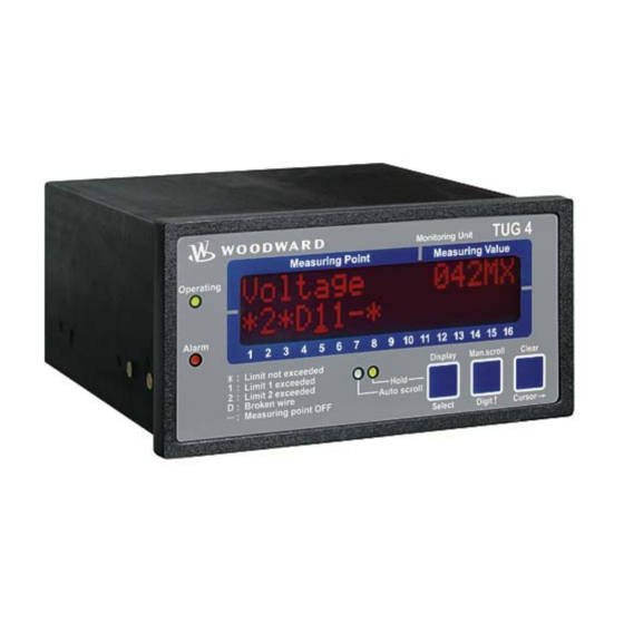
Manual 37303A Temperature Monitoring Unit - TUG 4 Chapter 7. Display and Control Elements Front Panel ≡≡≡≡≡≡≡≡≡≡≡≡≡≡≡≡≡≡≡≡≡≡≡≡≡ The touch-sensitive front panel has a plastic coating. All keys have been designed as touch-sensitive membrane keys. The Liquid Crystal display displays 2 rows × 16 characters that are indirectly illuminated in red. The con- trast of the display can be infinitely adjusted with a rotary potentiometer positioned on the left. -
Page 23: Leds
Manual 37303A Temperature Monitoring Unit - TUG 4 LEDs ≡≡≡≡≡≡≡≡≡≡≡≡≡≡≡≡≡≡≡≡≡≡≡≡≡ Readiness for operation Color "GREEN" "Operating" The LED "Operating" indicates the operating mode and the measurment monitoring is performed according to the configured values. Alarm message Color "RED" "Alarm" Alarm messages are indicated by the LED "Alarm" as follows: Continuous..The alarm has been acknowledged and is still present. -
Page 24: Lc Display
Manual 37303A Temperature Monitoring Unit - TUG 4 Clear / Cursor→ "Clear" → "Cursor " Clear ....Alarm messages are deleted by pressing this button. This function is de- Button scribed in detail on page 21 in the section titled "Acknowledgement". -
Page 25: Chapter 8. Configuration
Manual 37303A Temperature Monitoring Unit - TUG 4 Chapter 8. Configuration To activate the configuration mode, press the "Man.scroll" and "Clear" buttons simultaneously. You can advance through the individual configuration screens by pressing the "Select" button while in the configura- tion mode. -
Page 26: Measuring Inputs
Manual 37303A Temperature Monitoring Unit - TUG 4 Enter code number 0000 to 9999 Enter code 0000 On accessing the configuration mode, a code number, which identifies the various users, is requested. The displayed number XXXX is a random number (RN) which is confirmed with the "Select"... -
Page 27: Pt100 Measuring Inputs
Manual 37303A Temperature Monitoring Unit - TUG 4 Pt100 Measuring Inputs Monitoring of measuring input 1 ON/OFF Input 1 ON.... The value of this input appears in the display, and monitoring is enabled. OFF..No display or monitoring are performed. -
Page 28: 0/4 To 20 Ma Measuring Inputs
Manual 37303A Temperature Monitoring Unit - TUG 4 0/4 to 20 mA Measuring Inputs Monitoring of measuring input 1 ON/OFF Input 1 ON ....The value of this input appears in the display, and monitoring is enabled. OFF ..No display or monitoring are performed. - Page 29 Manual 37303A Temperature Monitoring Unit - TUG 4 Monitoring input function high limit / low limit monitoring Monit. input 1 high limit mon The monitoring function can be configured as follows: high limit... The configured threshold must be exceeded in order to generate an alarm message.
-
Page 30: Discrete Inputs
Manual 37303A Temperature Monitoring Unit - TUG 4 Discrete Inputs ≡≡≡≡≡≡≡≡≡≡≡≡≡≡≡≡≡≡≡≡≡≡≡≡≡ Function of discrete input acknowledge release/ energize to ack. Acknowledge Energize to ack. energize to ack..The Discrete Input acknowledge will be enabled by a changing from a high signal to a low signal. -
Page 31: Interfaces (Option Su)
Manual 37303A Temperature Monitoring Unit - TUG 4 Interfaces (Option Su) ≡≡≡≡≡≡≡≡≡≡≡≡≡≡≡≡≡≡≡≡≡≡≡≡≡ Interface configuration YES/NO Configure Interface YES..The interface can be configured and is enabled. The subse- quent parameters of this function are displayed. NO... Interface function is disabled and the subsequent parameters of this function are not displayed. -
Page 32: Screens For Protocol Mod Bus Rtu Slave
Manual 37303A Temperature Monitoring Unit - TUG 4 Screens for Protocol MOD Bus RTU Slave Device number MOD Bus RTU Slave 1 to 255 Device number MOD-Bus Device number for the MOD Bus RTU Slave. Baud rate MOD Bus RTU Slave 1.200 / 2.400 / 4.800 / 9.600 / 19.200... -
Page 33: Chapter 9. Commissioning
Manual 37303A Temperature Monitoring Unit - TUG 4 Chapter 9. Commissioning DANGER When commissioning the control, please observe all safety rules that apply to the handling of live equipment. Ensure that you know how to provide first aid in the event of an uncontrolled release of en- ergy and that you know where the first aid kit and the nearest telephone are. -
Page 34: Chapter 10. Technical Data
Manual 37303A Temperature Monitoring Unit - TUG 4 Chapter 10. Technical Data Ambient variables --------------------------------------------------------------------------------------------- Power supply (V ) ................24 Vdc (18 to 30 Vdc) Intrinsic consumption..................max. 10 W Ambient temperature for storage ..........-30 to +80 °C / -22 to +176 °F Ambient temperature for operation.........-20 to +70 °C / -4 to +158 °F... - Page 35 Manual 37303A Temperature Monitoring Unit - TUG 4 Housing --------------------------------------------------------------------------------------------------------- Type....................APRANORM DIN 43 700 Dimensions (B × H × T)................ 144 × 72 × 118 mm Front panel cutout (B×H) ............138 [+1.0] × 68 [+0.7] mm Connection....screw terminals depending on connector strip 1.5 mm² or 2.5 mm²...
-
Page 36: Appendix A. Interface (Option Su)
Manual 37303A Temperature Monitoring Unit - TUG 4 Appendix A. Interface (Option Su) Transmitting Telegram ≡≡≡≡≡≡≡≡≡≡≡≡≡≡≡≡≡≡≡≡≡≡≡≡≡ Number Content (Words) Unit/Bit Remark 3964 MOD bus CAN bus Profibus Byte Word Word Byte Telegram type "501" MUX=1 Measuring input 1 (14/15/16) °C... - Page 37 Manual 37303A Temperature Monitoring Unit - TUG 4 Number Content (Words) Unit/Bit Remark 3964 MOD bus CAN bus Profibus 36/37 Measuring input active (ON) Bit 15 Measuring input 16 MUX=7 Bit 14 Measuring input 15 Bit 13 Measuring input 14...
- Page 38 Manual 37303A Temperature Monitoring Unit - TUG 4 Number Content (Words) Unit/Bit Remark 3964 MOD bus CAN bus Profibus 42/43 Threshold 2 alarm is present Bit 15 Measuring input 16 MUX=8 Bit 14 Measuring input 15 Bit 13 Measuring input 14...
- Page 39 Manual 37303A Temperature Monitoring Unit - TUG 4 Number Content (Words) Unit/Bit Remark 3964 MOD bus CAN bus Profibus 48/49 Threshold 2 alarm is or has been Bit 15 Measuring input 16 MUX=9 but has not been Bit 14 Measuring input 15 acknowledged yet.
-
Page 40: Receiving Telegram (Profibus Dp)
Manual 37303A Temperature Monitoring Unit - TUG 4 Receiving Telegram (Profibus DP) ≡≡≡≡≡≡≡≡≡≡≡≡≡≡≡≡≡≡≡≡≡≡≡≡≡ The remote control data are only accepted by the TUG 4 if the device is equipped with the corresponding option. Number Content (Words) Unit/Bit Remark 00/01 Bus mode Bit 15 Internal (should be set to "0"... -
Page 41: Receiving Telegram (Modbus Rtu Slave)
Manual 37303A Temperature Monitoring Unit - TUG 4 Receiving Telegram (Modbus RTU Slave) ≡≡≡≡≡≡≡≡≡≡≡≡≡≡≡≡≡≡≡≡≡≡≡≡≡ The remote control data are only accepted by the TUG 4 if the device is equipped with the corresponding option. Number Content (Words) Unit/Bit Remark Internal... -
Page 42: General Data For The Interfaces
Manual 37303A Temperature Monitoring Unit - TUG 4 General Data for the Interfaces ≡≡≡≡≡≡≡≡≡≡≡≡≡≡≡≡≡≡≡≡≡≡≡≡≡ General Data for Procedure 3964 (TTY, RS-232, RS-485) Data Length of characters 8 Bit Stopbit 1 Bit Parity bit 1 Bit with even parity Data format... -
Page 43: Appendix B. Revision History
Manual 37303A Temperature Monitoring Unit - TUG 4 Appendix B. Revision History Version Modification valid from Modification number Date Serial number Documentation 1.6000/ 2004-08-19 New .... TUG 4/ Su GR 37303 Modbus Interface Revision NEW 2.6000 Hardware version 2.6xxx replaces previous version 1.6xxx... -
Page 44: Appendix C. Parameter List
Manual 37303A Temperature Monitoring Unit - TUG 4 Appendix C. Parameter List Device number P/N _____________________________ Rev ______________________________ Version _____________________________________________________________________ Project _____________________________________________________________________ Serial number S/N _______________ Date _____________________________ Parameter Adjustment range Default value Customer settings Option german/english english Language 1.6xxx... - Page 45 Manual 37303A Temperature Monitoring Unit - TUG 4 Parameter Adjustment range Default value Customer settings Option ONFIGURATION OF THE EASURING NPUTS Pt100-Measuring input 3 YES/NO Configure Input 3 ON/OFF Input 3 user defined No.3 Text Input 3 -999 to 999 °C 100 °C...
- Page 46 Manual 37303A Temperature Monitoring Unit - TUG 4 Parameter Adjustment range Default value Customer settings Option ONFIGURATION OF THE EASURING NPUTS 0/4 to 20 mA-Measuring input 6 YES/NO Configure Input 6 ON/OFF Input 6 user defined No.6 -0000 Text+unit Input 6...
- Page 47 Manual 37303A Temperature Monitoring Unit - TUG 4 Parameter Adjustment range Default value Customer settings Option ONFIGURATION OF THE EASURING NPUTS Pt100-Measuring input 10 YES/NO Configure Input 10 ON/OFF Input 10 user defined No.10 Text Input 10 -999 to 999 °C 100 °C...
- Page 48 Manual 37303A Temperature Monitoring Unit - TUG 4 Parameter Adjustment range Default value Customer settings Option ONFIGURATION OF THE EASURING NPUTS 0/4 to 20 mA-Measuring input 13 YES/NO Configure Input 13 ON/OFF Input 13 user defined No.13 –0000 Text+unit Input 13...
- Page 49 Manual 37303A Temperature Monitoring Unit - TUG 4 Parameter Adjustment range Default value Customer settings Option ONFIGURATION OF THE EASURING NPUTS 0/4 to 20 mA-Measuring input 16 YES/NO Configure Input 16 ON/OFF Input 16 user defined No.16 -0000 Text+unit Input 16...
-
Page 50: Appendix D. Service Options
≡≡≡≡≡≡≡≡≡≡≡≡≡≡≡≡≡≡≡≡≡≡≡≡≡ If a control (or any part of an electronic control) is to be returned to Woodward for repair, please contact Wood- ward in advance to obtain a Return Authorization Number. When shipping the unit(s), attach a tag with the fol- lowing information: •... -
Page 51: Packing A Control
Stuttgart [+49 (711) 789 54-0]. They will help expedite the processing of your order through our distributors or local service facility. To expedite the repair process, contact Woodward in advance to obtain a Return Authoriza- tion Number, and arrange for issue of a purchase order for the unit(s) to be repaired. No work can be started until a purchase order is received. -
Page 52: How To Contact Woodward
+49 (711) 789 54-100 e-mail: stgt-info@woodward.com For assistance outside Germany, call one of the following international Woodward facilities to obtain the address and phone number of the facility nearest your location where you will be able to get information and service. Facility... -
Page 53: Engineering Services
Temperature Monitoring Unit - TUG 4 Engineering Services ≡≡≡≡≡≡≡≡≡≡≡≡≡≡≡≡≡≡≡≡≡≡≡≡≡ Woodward Industrial Controls Engineering Services offers the following after-sales support for Woodward products. For these services, you can contact us by telephone, by e-mail, or through the Woodward website. • Technical support •... -
Page 54: Technical Assistance
Manual 37303A Temperature Monitoring Unit - TUG 4 Technical Assistance ≡≡≡≡≡≡≡≡≡≡≡≡≡≡≡≡≡≡≡≡≡≡≡≡≡ If you need to telephone for technical assistance, you will need to provide the following information. Please write it down here before phoning: Contact Your company____________________________________________________ Your name_______________________________________________________ Phone number ____________________________________________________... - Page 55 Phone +49 (711) 789 54-0 • Fax +49 (711) 789 54-100 stgt-info@woodward.com Homepage http://www.woodward.com/power Woodward has company-owned plants, subsidiaries, and branches, as well as authorized distributors and other authorized service and sales facilities throughout the world. Complete address/phone/fax/e-mail information for all locations is available on our website (www.woodward.com).
Need help?
Do you have a question about the TUG 4 and is the answer not in the manual?
Questions and answers