Table of Contents
Advertisement
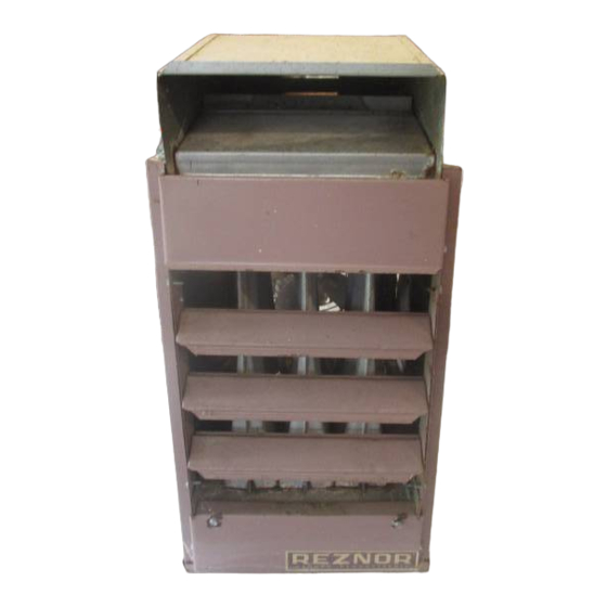
POWER VENT KIT INSTALLATION FOR DUCT FURNACES
AND OBSOLETE MODELS (H)CX, DX, (H)XE, AND (H)CXE
GENERAL INFORMATION . . . . . . . . . . . . . . . . . . . . . . . . . . . . . . . . . . . . . . . . . . . . . . . . . . . . . . . . . . . . . . . . . . . .1
Applicability . . . . . . . . . . . . . . . . . . . . . . . . . . . . . . . . . . . . . . . . . . . . . . . . . . . . . . . . . . . . . . . . . . . . . . . . . . . . . .1
Important Safety Information . . . . . . . . . . . . . . . . . . . . . . . . . . . . . . . . . . . . . . . . . . . . . . . . . . . . . . . . . . . . . . . . .1
POWER VENT KITS . . . . . . . . . . . . . . . . . . . . . . . . . . . . . . . . . . . . . . . . . . . . . . . . . . . . . . . . . . . . . . . . . . . . . . . . .2
Voltage . . . . . . . . . . . . . . . . . . . . . . . . . . . . . . . . . . . . . . . . . . . . . . . . . . . . . . . . . . . . . . . . . . . . . . . . . . . . . . . . . .2
Kit Selection . . . . . . . . . . . . . . . . . . . . . . . . . . . . . . . . . . . . . . . . . . . . . . . . . . . . . . . . . . . . . . . . . . . . . . . . . . . . . .2
Venter Assembly . . . . . . . . . . . . . . . . . . . . . . . . . . . . . . . . . . . . . . . . . . . . . . . . . . . . . . . . . . . . . . . . . . . . . . . . . .3
Control System . . . . . . . . . . . . . . . . . . . . . . . . . . . . . . . . . . . . . . . . . . . . . . . . . . . . . . . . . . . . . . . . . . . . . . . . . . . .4
Venter Adapter . . . . . . . . . . . . . . . . . . . . . . . . . . . . . . . . . . . . . . . . . . . . . . . . . . . . . . . . . . . . . . . . . . . . . . . . . . . .4
Power Venter Sequence of Operation . . . . . . . . . . . . . . . . . . . . . . . . . . . . . . . . . . . . . . . . . . . . . . . . . . . . . . . . . .5
KIT INSTALLATION . . . . . . . . . . . . . . . . . . . . . . . . . . . . . . . . . . . . . . . . . . . . . . . . . . . . . . . . . . . . . . . . . . . . . . . . .5
VENTING . . . . . . . . . . . . . . . . . . . . . . . . . . . . . . . . . . . . . . . . . . . . . . . . . . . . . . . . . . . . . . . . . . . . . . . . . . . . . . . . . .9
Specific Venting Requirements . . . . . . . . . . . . . . . . . . . . . . . . . . . . . . . . . . . . . . . . . . . . . . . . . . . . . . . . . . . . . . .9
Connecting Vent Cap To Double-Wall (Type B) Vent Terminal Pipe . . . . . . . . . . . . . . . . . . . . . . . . . . . . . . . . . .12
Connecting Single-Wall Vent Run to Double-Wall (Type B) Vent Terminal Pipe . . . . . . . . . . . . . . . . . . . . . . . . .12
OPERATIONAL TESTING . . . . . . . . . . . . . . . . . . . . . . . . . . . . . . . . . . . . . . . . . . . . . . . . . . . . . . . . . . . . . . . . . . .12
REPLACEMENT PARTS . . . . . . . . . . . . . . . . . . . . . . . . . . . . . . . . . . . . . . . . . . . . . . . . . . . . . . . . . . . . . . . . . . . . .13
This optional power venter is a motorized vent exhauster designed to permit the installation of a gravity-vented heater
in an area of negative pressure up to 0 .15 IN WC or where horizontal venting is required .
Applicability
NOTE: Models with the H prefix are standard and are not listed separately throughout this manual .
The venter assembly in this instruction form is designed to be installed only on the following equipment:
• Models X/DX/HX and CX/HCX: duct furnace
• Models XE/HXE and CXE/HCXE: packaged duct furnace and blower
• Models
XL/CXL and XLB/CXLB: fan and blower type unit heaters (power venter cannot be installed on model
XLB/CXLB units in sizes 030-105 when equipped with an optional blower cabinet)
Important Safety Information
• Refer to the installation manual provided with the unit for important safety information .
• Pay attention to all dangers, warnings, cautions, and notes highlighted in this manual . Safety markings should not
be ignored and are used frequently throughout to designate a degree or level of seriousness .
Improper installation, adjustment, alteration, service, or maintenance can cause property damage,
injury, or death . Read the installation, operation and maintenance instructions thoroughly before
installing or servicing this equipment .
OPTIONS CA1, CA2, CA3, AND CA4 FOR MODEL X
TABLE OF CONTENTS
GENERAL INFORMATION
⚠ DANGER ⚠
Revision: X-CA1,2,3,4 (01-22) 136958-A
Supersedes: X-CA1,2,3,4 (11-21) 136958-A
Advertisement
Table of Contents

Related Manuals for Reznor XL30


Summary of Contents for Reznor XL30
-
Page 1: Table Of Contents
Revision: X-CA1,2,3,4 (01-22) 136958-A Supersedes: X-CA1,2,3,4 (11-21) 136958-A POWER VENT KIT INSTALLATION FOR DUCT FURNACES OPTIONS CA1, CA2, CA3, AND CA4 FOR MODEL X AND OBSOLETE MODELS (H)CX, DX, (H)XE, AND (H)CXE TABLE OF CONTENTS GENERAL INFORMATION . . . . . . . . . . . . . . . . . . . . . . . . . . . . . . . . . . . . . . . . . . . . . . . . . . . . . . . . . . . . . . . . . . . .1 Applicability . -
Page 2: Power Vent Kits
GENERAL INFORMATION—CONTINUED Important Safety Information—Continued ⚠ WARNING ⚠ • The optional power venter and venter flue adapter are designed for USE WITH THESE DESIGNATED PRODUCTS ONLY . • DO NOT install these power venters on any other equipment including model F or B gravity-vented unit heaters (use only the power venting kits that are especially designed for F and B models) . -
Page 3: Venter Assembly
Table 3 . Power Vent Kit Components for Obsolete Models Unit Size Component Model Option 030–105 225, 250 350, 400 XL/XLB 136961 136962 — 136961 136962 136962 136963 — CXL/CXLB — 136961 XL/XLB 136968 136969 — 136968 136969 136969 136970 —... -
Page 4: Control System
POWER VENT KITS—CONTINUED Venter Assembly—Continued Table 6 . Venter Assembly Electrical Specifications Voltage Amps Shipping Weight (LB) Control Full Load Locked Rotor Motor 29992 1 .4 1 .94 29994 30229 0 .72 0 .95 30233 30231 0 .7 0 .94 30235 Motor is 2-pole with nominal 3,000 RPM and maximum permissible voltage of 127V for 115V unit, 228V for 208V unit, and 250V for 230V unit . -
Page 5: Power Venter Sequence Of Operation
Power Venter Sequence of Operation Before installation, it is helpful to understand the fundamental operation and sequencing of the power venter as follows: 1 . Venter’s relay coil is wired in series with thermostat—when thermostat calls for heat, thermostat contacts close circuit . - Page 6 KIT INSTALLATION—CONTINUED DETAIL A DETAIL B DETAIL C Figure 3 . Flue Adapter and Venter Assembly Installation ⚠ CAUTION ⚠ DO NOT position the venter with the discharge outlet (vent connection) pointing in a direction below horizontal . NOTE: The venter assembly is assembled and wired at the factory . It includes the blower, motor, capacitor, pressure switch, thermal switch, and junction box .
- Page 7 b . For units with vertical (top) flue (see Figure 3, DETAIL C): (1) Position venter assembly on vent pipe elbow with venter discharge outlet (vent connection) pointing in horizontal to vertical direction . (2) While holding venter assembly in place, drill hole through connecting overlap in top portion of venter assembly and vent pipe elbow .
- Page 8 - BLOWER MOTOR REMAINS ON AS DETERMINED BY FAN TIME DELAY. WIRING IN VENTER (SHIPPED SEPARATE) NOTES - THE FOLLOWING CONTROLS ARE SUPPLIED BY REZNOR FOR FIELD INSTALLATION: VENTER 1, 4, 6, 7, 8, - THE FOLLOWING CONTROLS ARE SUPPLIED AS OPTIONAL EQUIPMENT: THERMOSTAT TERMINAL BLOCK -- HEATER COMPARTMENT 10, 11, B &...
-
Page 9: Venting
PRESSUR E Figure 6 . Wiring Diagram for Unit with Match-Lit Pilot (Applies to Units Manufactured After JUL 2012 with Sail Switch Replaced by Pressure Switch) VENTING ⚠ DANGER ⚠ If this furnace is replacing an existing furnace, ensure that the vent is properly sized for the furnace being installed . - Page 10 VENTING—CONTINUED Specific Venting Requirements—Continued Table 7 . Pipe Dimensions Unit Size Vent Diameter 030–150 (Inches (mm)) Maximum Length (Feet (Meters) 4 (102) 100 (30) 75 (23) 50 (15) 35 (11) 30 (9) 15 (4 .5) — — 6 (152) — —...
- Page 11 Single-Wall Vent/Single-Wall Terminal Single-Wall Vent/Double-Wall Terminal Figure 8 . Horizontal Vent Terminal ⚠ DANGER ⚠ If the vent terminal is to be installed near ground level, position it at least 6 inches above maximum anticipated snow depth . NOTE: Products of combustion can cause discoloration of some building finishes and deterioration of masonry materials .
-
Page 12: Connecting Vent Cap To Double-Wall (Type B) Vent Terminal Pipe
VENTING—CONTINUED Connecting Vent Cap To Double-Wall (Type B) Vent Terminal Pipe 1 . Position vent cap at exhaust end of double wall pipe—refer to flow arrow on vent pipe . 2 . Slide vent cap inside pipe . 3 . Drill hole—slightly smaller than screw being used—through overlap of vent cap and pipe . 4 . -
Page 13: Replacement Parts
REPLACEMENT PARTS NOTES: • Currently-manufactured venter assemblies used in these power vent kits have 24V controls and are identified by the prefix LV (LV301 and LV401) . • Obsolete venter assemblies with the prefix V have line voltage controls . These models are no longer available, but replacement parts are the same as those listed for low-voltage models (see Figure 4) . - Page 14 NOTES X-CA1,2,3,4 (01-22) 136958-A...
- Page 15 NOTES X-CA1,2,3,4 (01-22) 136958-A...
- Page 16 Specifications and illustrations subject to change without notice or incurring obligations . Latest version of this manual is available at www .reznorhvac .com . ©2022 Nortek Global HVAC LLC, O’Fallon, MO . All rights reserved . X-CA1,2,3,4 (01-22) 136958-A...
Need help?
Do you have a question about the XL30 and is the answer not in the manual?
Questions and answers