Table of Contents
Advertisement
Quick Links
Quick Guide
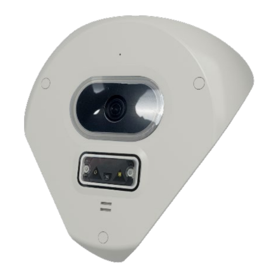
Roughneck AI V2005CNR-W24IR
Corner Mount Camera
XX331-20-00
Cybersecurity Notification: All network connected devices should use best practices for accessing the
device. To that end, these network cameras do not have a default password. A user defined password with
minimum password strength requirements must be set to access the device. See page 16 of this Quick Guide
for set-up instructions.
Be sure to check Vicon's website to be see if you have the most up-to-date camera firmware.
Vicon Industries Inc. does not warrant that the functions contained in this equipment will
meet your requirements or that the operation will be entirely error free or perform precisely as
described in the documentation. This system has not been designed to be used in
life-critical situations and must not be used for this purpose.
Document Number: 8009-8331-20-00 Rev: 2/23
Product specifications subject to change without notice
Copyright © 2023 Vicon Industries Inc. All rights reserved.
Vicon Industries Inc.
Tel: 631-952-2288) Fax: 631-951-2288
Toll Free: 800-645-9116
24-Hour Technical Support: 800-34-VICON
UK: 44/(0) 1489-566300
www.vicon-security.com
(800-348-4266)
Advertisement
Table of Contents

Summary of Contents for VICO AI V2005CNR-W24IR
- Page 1 Quick Guide Roughneck AI V2005CNR-W24IR Corner Mount Camera XX331-20-00 Cybersecurity Notification: All network connected devices should use best practices for accessing the device. To that end, these network cameras do not have a default password. A user defined password with minimum password strength requirements must be set to access the device.
-
Page 2: Table Of Contents
V2005CNR-W24IR Corner-Mount Camera | Quick Guide Table of Content Product Overview Physical Characteristics Installation and Mounting Package Contents Installation 2.2.1 Checking Appearance 2.2.2 Inserting or Removing the SD Card 2.2.3 Connecting the Cables 2.2.4 Installing the Camera onto a Wall Connection Network System Requirements... - Page 3 V2005CNR-W24IR Corner-Mount Camera | Quick Guide WARNING This camera operates at 12 VDC/24 VAC/PoE (IEEE 802.3af Class 3). Installation and service should be performed only by qualified and experienced technicians and comply with all local codes and rules to maintain your warranty. We are NOT liable of any damage arising either directly or indirectly from inappropriate installation which ...
- Page 4 V2005CNR-W24IR Corner-Mount Camera | Quick Guide FCC Compliance Statement Information to the user: This unit has been tested and found to comply with the limits for a Class A digital device pursuant to Part 15 of the FCC Rules. Operation is subject to the following two conditions: (1) this device may not cause harmful interference, and (2) this device must accept any interference received, including interference that may cause undesired operation.
-
Page 5: Product Overview
V2005CNR-W24IR Corner-Mount Camera | Quick Guide 1 Product Overview 1.1 Physical Characteristics 2.4 (60) 8.2 (208) Figure1-1:Physical Dimensions [in. (mm)]... - Page 6 V2005CNR-W24IR Corner-Mount Camera | Quick Guide Figure 1 - 2: Parts Pictorial Index Description Camera Top Cover Camera Module Bottom case Table 1-2: Parts Pictorial Index Description...
- Page 7 V2005CNR-W24IR Corner-Mount Camera | Quick Guide Figure 1-4: Parts Pictorial Index Table 1-4: Internal Interface Index Description Name Description Default: Press the button for 5 seconds to restore the camera settings Default Button to factory default. Reset: Press the button for approximately 1 second to reboot the Reset Button camera.
-
Page 8: Installation And Mounting
2 Installation and Mounting 2.1 Package Contents Check if all the items listed below are included in the packing box. Camera * 1 Grommet *3 Plastic Anchor * 3 T20 Torx Wrench * 1 T20 Stop Screw * 3 Desiccant * 2 8-pin Terminal Connector (for I/O function) * 1 2-pin Terminal Block * 1 Printed Quick Guide * 1... -
Page 9: Inserting Or Removing The Sd Card
2.2.2 Inserting or Removing the SD Card Loosen the 3 T10 captive screws, turning counterclockwise using the Torx wrench. Carefully pull open the micro SD card cover and insert or remove the micro SD card into or from the camera. Note: It is recommended to reboot the camera after inserting the micro SD card. -
Page 10: Connecting The Cables
2.2.3 Connecting the Cables Remove the rubber tabs from the rubber grommet on the bottom case by simply pulling the tabs off to access the holes. Pull all cables through the cable holes of rubber grommet. Figure 2-2: Pull All Cables through Cable Hole Terminate the cables with connectors and terminal block (provided) and connect each cable to the corresponding power port. - Page 11 With the camera cover tilted slightly upward, the I/O interfaces are easily accessed below the camera module. Make the appropriate connections. Based on your needs, connect the power cable to the power port via one of the following 3 options. PoE (Class 3): Connect an Ethernet cable terminated with an RJ-45 connector to the PoE RJ-45 ...
-
Page 12: Installing The Camera Onto A Wall
2.2.4 Installing the Camera onto a Wall Use the bottom case to mark the location for the three mounting holes. Drill three holes on the selected mounting surface. Figure 2-4: Drill Holes on the Surface Insert three plastic anchors (provided) into the three holes. Figure 2-5: Insert Plastic Anchors... - Page 13 Align the three holes on the bottom case with the three holes on the wall and use the Torx wrench to fasten the three T20 Torx screws, turning clockwise into the plastic anchors, to securely fix the camera to the wall. Figure 2-6: Install the Camera onto the Wall Attach two desiccants (supplied) into the noted two locations of the top cover;...
- Page 14 Hold the camera top cover up to the camera module and align the three holes on the camera top cover with the three holes on the camera module. Figure 2-8: Installing the Camera Module Re-tighten the three captive Torx screws into the three holes, turning clockwise using the Torx wrench. Figure 2-9: Insert and Fasten the Torx Screws...
- Page 15 Insert the 3 rubber grommets (supplied) into the three holes on the camera top cover to seal the screw holes. Figure 2-10: Insert the Grommets...
-
Page 16: Connection
V2005CNR-W24IR Corner-Mount Camera | Quick Guide 3 Connection Network The camera, which is equipped with Ethernet RJ-45 network interface, can deliver live view image in real time via both Internet and Intranet. System Requirements The table below lists the minimum requirements to implement and operate the camera. It is recommended not to use any hardware/software component below these requirements for proper performance. -
Page 17: Connecting Process
V2005CNR-W24IR Corner-Mount Camera | Quick Guide Connecting Process 3.3.1 Accessing the Camera The camera can be accessed directly from its web page or using Vicon’s PRONTO Device Manager, which can be found on Vicon’s website. Note that when accessing the camera for the first time, a message will display to reset the password. -
Page 18: Pronto Device Manager
V2005CNR-W24IR Corner-Mount Camera | Quick Guide PRONTO Device Manager PRONTO is Vicon’s device manager (Discovery tool) that can be used to discover all Vicon cameras on a system. The complete User Manual can be found on Vicon’s website. Figure 3 - 2: PRONTO Interface Upon startup of the PRONTO Device Manager, the tool’s auto-discovery function generates a list of •...
Need help?
Do you have a question about the AI V2005CNR-W24IR and is the answer not in the manual?
Questions and answers