
Summary of Contents for Automation Controls Group UniDrive SCC-3
- Page 1 Installation and Troubleshooting Guide UniDrive Smart Conveyor Control ® Generation III (SCC-3) Product 110515...
-
Page 2: Table Of Contents
Copyright ©2013-2018 Automation Controls Group, Inc. A division of MEC Companies, Inc. All Rights Reserved. This document is the property of Automation Controls Group, Inc., and may not be reproduced in whole or in part without prior written approval. Other trademarks and service marks used or referenced in this document are the property of their respective owners. - Page 3 L I S T O F F I G U R E S Figure 1: SCC-3 Controller Components ....................4 Figure 2: Motor Connector Orientation ....................5 Figure 3: Firmware Version Display Example ..................10 L I S T O F T A B L E S Table 1: DC Power Inputs Pinout......................
-
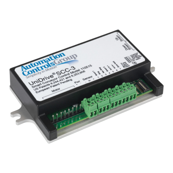
Page 4: Product Diagram
Product Diagram Figure 1: SCC-3 Controller Components 1) Motor Connection Header 2) +24V DC Power Input Header (plug included) 3) PNP Sensor Connection Header (plug included) 4) Smart/User Input-Output Connection Header (plug included) 5) Feedback LED Indicators 6) Configuration Switches 7) Upstream Peer-to-Peer NPN RJ-25 Connection 8) Downstream Peer-to-Peer NPN RJ-25 Connection 9) Mounting Plate/Heat Sink... -
Page 5: General Notes
UniDrive® motors and controls are designed to operate together as Table 1: DC Power Inputs Pinout a complete and compatible drive system. Proper care must be taken to prevent damage to the Automation Controls Group (ACG) NOTE: When adjacent zones are operating from separate control, motor and connection cable. -
Page 6: Feedback Led Indicators
Feedback LED Indicators CAUTION: If mounting the control on a curved section of The control board contains four (4) LED feedback indicators: conveyor, use washers between the mounting plate and the conveyor frame. This is to assure that the mounting One (1) Fuse LED plate is not distorted, causing damage to the enclosed... -
Page 7: Mount The Control
Mount the Control Configure the Operating Mode Mount the control in a location where the motor cable Identify the operating mode that this section of conveyor will reaches the connection header without putting strain on the use for transporting objects and then set Switch 2. cable connector or the header. -
Page 8: Connect User Input/Output
Connect User Input/Output NOTE: When this signal is active, parcels are pushed out of the upstream end of the conveyor regardless of the availability of any upstream device to accept the parcels. Entry Zone 3.8.1 In this scenario, if there is nothing there, any parcels could potentially fall to the floor. -
Page 9: Braking & Zero Motion Hold (Zmh)
All objects in the upstream zones will also be held while the Braking & Zero Motion Hold (ZMH) 3.8.4 zone hold input is active. When an object is actively exiting the zone hold input will have When DIP Switch 8 is placed in the OFF position, motor no effect on that object exiting. -
Page 10: After Removal Of A Slug Signal
Four (4) flashes in 4 seconds: There is a problem with the After Removal of a Slug Signal 4.3.3 motor cable or connection. Check to see that the cable is not damaged and that all of the wires are secure. (If Rev Slug is Not Active) Five (5) flashes in 4 seconds: Control over temperature. -
Page 11: 6-Wire Modular Cable Orientation
RJ25,6-Wire,Modular Cable Orientation, L<10ft Additional Assistance To request the latest revision to our user manual, visit our website at www.automationcontrolsgroup.com. For additional assistance, please contact our National Sales Manager at (414)-426-6539 or our Application Engineering Department for assistance at (619) 677-6530. Document Revision History Rev: Date: Summary:...
Need help?
Do you have a question about the UniDrive SCC-3 and is the answer not in the manual?
Questions and answers