
Related Manuals for Pennsylvania 7600E

Summary of Contents for Pennsylvania 7600E
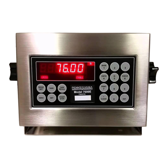
- Page 1 Pennsylvania Scale Co. 1042 New Holland Ave. Lancaster 17601 800-233-0473 www.pascale.com INSTRUCTION & SERVICE MANUAL 7600E Digital Indicator V2.84...
-
Page 2: Table Of Contents
TABLE OF CONTENTS SPECIFICATIONS………………………………………3 INSTALLATION…………………………………………4 SETUP ACCESS………………………………………..5 MENU LAYOUT...………………………………………6 CONFIGURATION……………………………………..7 REMOTE SERIAL DISPLAY………………………….8 CALIBRATION………………………………………….9 SERIAL PORTS………………………………………10 SERIAL COMMUNICATIONS……………………….11 ANALOG OUTPUT……………………………………13 DIGITAL INPUT/OUTPUT……………………………15 SETPOINTS……………………………………………16 OVER/UNDER…………………………………………17 BATCH MODE…………………………………………18 SERIAL COM. SETPOINT/ACC……………………...19 TIME & DATE………………………………………….20 WEIGH IN/OUT………………………………………..21 SMART SERIAL……………………………………….23 ASCII CHART………………………………………….28 DISPLAY MESSAGES………………………………..32 115/220 VAC…………………………………………..33 SPARE PARTS………………………………………..34... -
Page 3: Specifications
SPECIFICATIONS Smart Serial Setup: 8 custom print files plus 8 macro files, 30 characters each. Batch Start/Stop: Control from front panel or remote input. Setpoint Operation: 4 output relays configurable for normal setpoints, over/under or manual/auto batch modes. LOAD CELL A/D CONVERTER TYPE: 24 bit delta sigma EXCITATION: 5 VDC, 120 mA max. -
Page 4: Installation
INSTALLATION POWER WIRING: The indicator is designed to be operated from 117/217 VAC, 50-60 Hz. The unit power cord must be plugged into a grounded 3 - wire polarized AC wall socket. All normal wiring and grounding precautions should be observed, including use of a "clean" AC power line. -
Page 5: Setup Access
SETUP ACCESS To access instrument configuration, calibration or to enable options, depress the “Zero” key for five seconds. The Audit Trail counters (“Pxxxx” and “Cxxxx”) are displayed first followed by access code request (“AC?”). The initial factory setting is “0000” which can be entered with four steps of the “Gross/Net”... -
Page 6: Menu Layout
Menu Layout Configuration: Divisions, count by, decimal, over range, filter, AZM, zero range, ISM, lb/kg, serial port selection, DIO enable Calibration: Zero, Span Analog Output: Gross, Net, Display; Zero, Span, Trim Setpoint DIO: Setpoint, Over/Under, Manual / Auto Batch Time & Date: 24 hr, 12 hr, Print format Weigh –... - Page 7 CONFIGURATION: “SEL.CFG” Use Gross/Net to enter the menu and step to each category, Tare Recall to select parameters. ENT to return to menu selection. Capacity is the combination of “1”, “2” and “3”. Example: 1__100, 2___2 and 3__0.0 = 2,000 x 0.2 lb Step Parameters Definition...
-
Page 8: Remote Serial Display
Remote Serial Display (RSD) Option In RSD mode the instrument can be set to work with another unit as a “remote” either as the main or the slave unit. Communication is pre-set for channel two only on both units. (RS232, 9600, 8, none) When in remote mode, re-access to the following selections requires using the internal “cal”... -
Page 9: Calibration
CALIBRATION: “SEL.CAL” Use Gross/Net to enter the menu indicated by a flashing “C” on the left and live weight is displayed. Scale zero (dead load) or adjusting span (single or multi- point) are independent. Therefore either can be done and repeated as necessary before exciting calibration. -
Page 10: Serial Ports
SERIAL PORTS Port 1: RS232 duplex (Rx,Tx), 20ma (Tx). Port 2: RS232 duplex (Rx,Tx), 20ma (Rx,Tx), RS485, or RS422. Note: Position jumper on J2 for Port 2 receive selection. Tx1, RS232 Rx1, RS232 Tx2, RS232 A-RS232 Rx2, RS232 B-20ma Tx1, -20ma C-RS485 D-RS422 Tx1,Tx2,+20ma (5 vdc) -
Page 11: Serial Communications
Serial Communications Remote Commands <Z><cr> Zero Scale “Gross” mode, no motion, inside zero range. <N><cr> Switch to Net “Gross” mode with Tare stored. <G><cr> Switch to Gross “Net” mode. <T><cr> Auto Tare Switch to Net, no motion, not at “Gross” zero. <P><cr>... - Page 12 G/N: One (1) character field data identification for weighing mode in continuous (computer) mode. Gross Mode = “G” (ASCII 071), Net Mode = “N” (ASCII 078) status: One (1) character data identification used in the continuous (computer) output mode to identify the status of the indicator. Characters are listed below in order of priority.
-
Page 13: Analog Output
OPTION 1: Analog Output 0 – 10 Vdc or 4 – 20 ma, select with jumpers J1 and J2 0.25A Transformer Line Filter EW-1000-AOUT TB 20 TB-1 EW-1000 Rev….. 0 – 10 Vdc or 4 – 20 ma Position J1 & J2 for V/I... - Page 14 Option 1 Analog Output: “SEL.OP1” Use Gross/Net to enter the menu and step to each category, Tare Recall to select parameters. ENT to return to menu selection. DISPLAY Parameters Definition 1.1__Gr Gr, Net, DSP Analog tracks gross, net or display “1.5__Zr”...
- Page 15 OPTIONS 2: DIO AC Inputs; D1, D2 are not installed, J1 = short (underside), J2 = open, R1 – R4 = 18k (3w, 5%, flame proof). DC Inputs; D1, D2 are installed, J1 = open (cut trace), J2 = short, R1 – R4 = 1.5k (1/2w, 5%, carbon film).
- Page 16 the weighing mode. Use Gross/Net to enter the menu and step to each category, Tare Recall to select parameters. ENT to return to menu selection. Note: external Inputs are enabled in Configuration with “CFG 30”. DIO Inputs can be configured for 120vac, 5vdc or dry contact. CFG 30 off Normal Batch...
-
Page 17: Setpoints
Mode select: setpoint, over/under (check OFF, SP, OU.UN, bAt1, bAt2 weighing), Manual Batch, Auto Batch Setpoint Off, s1, s1.p, s1.d, s.p.d, Dual Setpoint. 1 + pre-act, + drib, + both, Set1-A&B. Gr, nt, dSP, Count Setpoint 1 tracks Gross, Net, Display, Count POS, ZER Output on below reading (POS), inverted (ZER) Off, s2, s2.p, s2.d, s2.p.d, tOL,... - Page 18 7400 uses print, tare or external (DIO) for start. Pressing any key other than “start” will pause and Prn, tAr, dln a second push will abort. 7600E uses Start/Stop panel switch Off, s1, s1.p, s1.d, s.p.d Setpoint. 1 + pre-act, + dribble, + both...
- Page 19 Totalizer/Accumulator reset command. Send TC<CR> to reset the totalizer, and the meter responds with a TC+<CR><LF> string. Ten/Nine-digit Accumulator Printing/Serial Format Output COMMAND Output Description TR1<CR> “ 57.85 lb” 10/9-digit w/ printable units (e.g., lb or kg) 10/9-digit w/ computer units (e.g., L or K) & A for TR2<CR>...
-
Page 20: Batch Mode
Set time: hh mm ss Set date: mm dd yy Month print selection, short numerical S.no, no, Let (mm/dd/yy), number 01 thru 12, month spelled Off, Un, Ab, On Print under, above or on the same line Weigh – In / Weigh - Out See page 19 10 Point Linearity On, Off see page 9... - Page 21 Operates in “Gross” only. This mode provides a system for single scale applications to determine net weight by storing incoming weight and completing the transaction with out going weight. Off, On Turn on Weigh–in / Weigh-out 1, 2 Select print port 1 or 2 Data setup, 8 bit no parity one stop, 7 bit even 8n1, 7e1, 7o1 one stop, 7 bit odd one stop...
- Page 22 Operator inserts ticket and pushes “Print” key. Display responds with “Id no” prompt. Operator enters truck “ID Number”, up to 6 – digits. Operator pushes “Ent” key. Printer prints: Time/Date (optional) (xxxxxx) ID. NO. (xxxxxx) lb GR Truck goes to empty load. Empty truck returns to scale, scale indicates “Stable”.
-
Page 23: Smart Serial
Select ID: With “ID” displayed, user can select a stored ID by pressing “Set” (up) or “Start/Stop” (down) to scroll through the buffer. Print Buffer: Pushing Gross/Net with ID displayed will cause output of the complete buffer ( ID with Tare). Clear ID: Pushing clear with ID displayed will clear that ID and step to the next. - Page 24 imported into the serial output data stream. CUSTOM PROTOCOL FILE SELECTION: The selection of the associated custom print file is performed automatically by serial port and the data mode (GROSS, NET, TOTAL RECALL, or SPECIAL) that the instrument is currently in at the time of a print. In other words, if Ports 1 & 2 were selected for demand print (dE) and the instrument was in the "GROSS"...
- Page 25 its default format (eg. file 7.1 off - the GROSS data from Port 1 is sent out in its default format). MACRO FILES (7.9 TO 7.16): There are eight (8) macro files that can be accessed in any of the prime Print Files 1 - 8 (7.1 to 7.8) using the "600"...
- Page 26 Off, On Enables smart serial Off, On Enables each print buffer 7.1…..7.16 Description Access buffer 7.1 and exit when done Use numeric keys to enter code 0-999 Enter code CLEAR Clear the code START/STOP Insert code TARE RECALL Clear entire (current) buffer GROSS/NET Steps to next buffer position TARE...
- Page 27 SSC (Smart Serial Codes) command is provided to read or write buffer data 7.1…7.16. Example: Read SSC<CR> SSC 1 2 600 200 32 601 13 10 999 SSC 9 83 99 114 97 112 32 105 110 99 46 13 10 999 SSC 10 402 32 401 999 Write SSC<sp><X><yyy><yyy><cr>...
- Page 28 CHAR CODE CHAR CODE CHAR CODE CHAR CODE " & < > ASCII CONTROL CODE CHART 2...
- Page 29 UPPER CASE UPPER CASE LOWER CASE LOWER CASE CHAR CODE CHAR CODE CHAR CODE CHAR CODE PARAMETER CONTROL CODE CHART...
- Page 30 CODE DESCRIPTION CODE DESCRIPTION GROSS WT & 'LB/KG GR' TRUCK GR0SS 'LB/KG GR' GROSS WT & 'LG/KG' TRUCK GROSS ONLY GROSS WT TRUCK TARE 'LB/KG TR' GROSS WT(no 0 blanking) TRUCK TARE ONLY TRUCK NET 'LB/KG NT' NET WT & 'LB/KG NT' TRUCK NET ONLY NET WT &...
-
Page 31: Display Messages
LINE DESCRIPTION LINE DESCRIPTION Option 8: AC/DC operation Off, On Enables battery charger Off, 5, 15, 30, 90, 120 Auto shutoff in minutes, timer resets with motion DISPLAY MESSAGES... - Page 32 MESSAGE DESCRIPTION D/A card detected - Displayed under the check function. IIC.ERR IIC short - Power-up hardware failure indication. EEPROM is reset by EER command - Power-up message Displayed on power-up when the DC power push-button is pressed. AUTO EEPROM is reset - Power-up message ERR6.x Key-pad key is stuck.
- Page 33 115 to 220 VAC Conversion : EW1000 Bottom Side CUT CLAD 2-Places ADD Jumper...
-
Page 34: Spare Parts
3434343434 Spare Parts Part No. Description 57819 Main Board 57512 Display Board 57860 Keypad Overlay 57675 Display Cable 56734 Load Cell T-Strip Conn. U-Bkt 56734 U-Bkt Knobs Enclosure 57811 Analog Output Setpoint AC input Setpoint DC input Second Channel...