Table of Contents
Advertisement
Quick Links
Advertisement
Table of Contents

Related Manuals for ZAHNER PAD4

Summary of Contents for ZAHNER PAD4
- Page 1 20/12/2022...
- Page 2 The user must make sure to discharge his-/herself from any electrical charge before touching the potentiostat (TIP: use grounded ESD-matts). Maintain the maximum input voltage of the device and the selected voltage range. Use electrically insulated thermocouples. Do not expose the PAD4 card to heat.
-
Page 3: Table Of Contents
2.4.1 2-Pole LEMO Jack (effective until July 2015) ......7 2.4.2 7-Pole LEMOSA Jack (effective from August 2015) ....8 3 Configuration .................... 9 3.1 Select PAD4 Channel for AC Voltage Display ........10 3.2 Select PAD4 Channels for EIS Measurement ........10 3.3 PAD4 Calibration ................11 3.4 Setup Customized Input Ranges ............ -
Page 4: Introduction
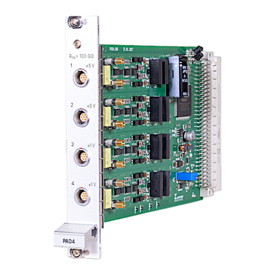
PAD4 is a plug-and-play card for an extension slot of the Zennium Pro/X. It allows connecting four different potential sense inputs for parallel impedance measurements. - Page 5 PAD4 Connection scheme for 8 channel PAD4 with an external power potentiostat PP211 (20 V / 10 A) connected via EPC42 to an IM6.
-
Page 6: Packing List
PAD4 The PAD4 AD converter card is also compatible with a 3 party electronic load interfaced from the IM6/Zennium by means of the FRA-Probe. 1.1 Packing List PAD4 addon card 4 sense cables (Lemosa plug to blue & green twisted cables) -
Page 7: Pad4: Technical Data
PAD4 2 PAD4: Technical Data 2.1 PAD4-HC Specifications Socket: 4x Lemosa EGA.0B.307.CLL Input Impedance: 100 KΩ ±4 V (standard configuration) Input Range: ±5 V, ±10 V, ±12 V, ±20 V or ±24 V on demand Offset Voltage: ±1.0 mV ±0.1% full scale Common Mode Range: ±100 V... -
Page 8: Pad4-Hz Specifications
1x 125 nV @ 4 mV AC amplitude 1 (ZENNIUM PRO) Maximum PAD4 Supported 4 (ZENNIUM X) 2.4 PAD4 Input Jack Pinout 2.4.1 2-Pole LEMO Jack (effective until July 2015) 1: upper connector female: + green (reference electrode) 2: lower connector male: - blue... -
Page 9: 7-Pole Lemosa Jack (Effective From August 2015)
PAD4 2.4.2 7-Pole LEMOSA Jack (effective from August 2015) 1: + green (reference electrode) 2: not connected 3: -5 V supply 4: +5 V supply 5: not connected 6: - blue (working electrode sense) 7: GND supply Note: ±5 V supply (pin 3,4,7) only required by CIMPS-MDTR photosense preamplifier. -
Page 10: Configuration
Click on the Z icon at the upper left edge of the Thales software window and switch to Control Potentiostat page. Click on Check Cell Connections. The Thales software detects the PAD4 cards automatically and shows the button Parallel Impedance Setup. Click on that button to switch to Synchronous... -
Page 11: Select Pad4 Channel For Ac Voltage Display
Setup customized input potential ranges Select channel for AC display. Activate/deactivate PAD4 channels. Enable activated channels for EIS. PAD4 calibration only for. 3.1 Select PAD4 Channel for AC Voltage Display Select channel for EIS AC voltage display green: main potentiostat red: selected PAD4 channel 3.2 Select PAD4 Channels for EIS Measurement... -
Page 12: Pad4 Calibration
Calibration menu. Select DC Offset & Gain to perform a DC calibration. 3.4 Setup Customized Input Ranges The standard input range of the Note: Special sense PAD4 addon cards is ±4 V. This cables with additional range increased with input... -
Page 13: Parallel Impedance Measurements
PAD4 channel Data display, realtime frequency domain displays and numerical displays only show measure data of the main potentiostat channel. A realtime impedance plot of the PAD4 channels during measurement easily be done with the Online Display. Select PAD4 channels (impedance [C01..C16], phase[C01..C16]) - Page 14 The PAD4 channels can be customized of a voltage range of ±4 V, ±5 V, ±10 V, ±12 V, ±20 V, and ±24 V. The compliance voltage range is also different for PAD4 with different voltage ranges.
-
Page 15: Parallel Impedance Analysis
PAD4 -14- 5 Parallel Impedance Analysis Click on the Z icon at the upper left edge of the Thales software window and navigate to EIS Analysis “SIM”. Select open series measurements. Select first impedance spectra measurement [filename]00.ism to open the hole parallel measurement data. -
Page 16: Dc Measurements And Signal Acquisition
Acquire data page. Here you can switch on/off acquisition data for all methods (logging on/off). 6.1 Create ACQ Channels for PAD4 Select “Edit Input” and click into the table below to open channel definition box. channel: [2..17] for PAD4 channel [1..16]...