Table of Contents
Advertisement
Advertisement
Table of Contents

Summary of Contents for Courtyard CY460
- Page 1 CY460 & CY460D Sync Pulse & Test Pattern Generator...
- Page 2 This document contains proprietary information which is protected by copyright. All rights are reserved. No part of this document may be photocopied, reproduced or translated into another language without the written prior consent of Courtyard Electronics Limited. © Courtyard Electronics Ltd 2012, 2013, 2014, 2015, 2016, 2017 Courtyard Electronics Limited 8 Campbell Court, Bramley, Hampshire RG26 5EG.
- Page 3 This Manual Scope This manual provides all the information you will need to effectively operate and maintain your CY460 Sync Pulse & Test Pattern Generator. It describes installation, operation, maintenance and troubleshooting. Locating Information Following this introduction is a Table of Contents that indicates on which page in this manual a topic can be found.
-
Page 4: Table Of Contents
Operating Basics ......................41 Front Panel Buttons and Indicators ................ 41 CY460 Sync Pulse and Test Pattern Generator – Front Panel Controls and Indicators . 41 Rear Panel Connectors ..................... 43 CY460 Sync Pulse and Test Pattern Generator – Rear Panel Connectors ....... 43 Operating Basics ....................... - Page 5 GPS Report ........................... 122 Configuration Menu ......................124 Network Menu ........................128 NTP Menu..........................130 PTP Menu ..........................130 DashBoard Menu ......................... 134 Backup Device Menu ......................136 SNMP Menu ......................... 130 Option Enable Menu ......................138 Calibration Menu ......................... 140 Troubleshooting .......................
- Page 6 28 February 2017 CY460_Operational_Manual_405 Page 6 of 218...
- Page 7 Contents This Manual Scope Locating Information Organisation Table of Contents Installation and Planning General Safety Summary Avoiding Fire or Personal Injury Symbols and Terms Environmental Considerations RoHS & WEEE Restriction of Hazardous Substances (RoHS) Waste Electrical and Electronic Equipment (WEEE) Equipment Recycling Preface About This Manual...
- Page 8 2.3 Operating Basics 2.4 Updating Software 3.0 Menu System 3.1 Menu Screens and Maps 3.2 Audio Menu 3.3 Video Menu 3.4 Timecode Menu 3.5 Genlock Menu 3.6 System Setup Menu 4.0 Troubleshooting 5.0 Warranty Appendices Appendix A Specifications Appendix B Connector Pinout Data Appendix C Appendix D...
- Page 9 CY460 SPG – TimeCode Figure 1.2e CY460 SPG – Module Interconnect Figure 2.1 CY460 Sync Pulse and Test Pattern Generator – Front Panel (Single Supply option) Figure 2.2 CY460 Sync Pulse and Test Pattern Generator – Rear Panel Figure 2.3 CY460 Sync Pulse and Test Pattern Generator –...
- Page 10 Table A.4 Frequency Reference Outputs Table A.5 1Hz Frequency Reference Output Table A.6 Analog Video Outputs Table A.7 Serial Digital Interface Table A.8 AES/EBU Audio Unbalanced Outputs Table A.9 AES/EBU Audio Balanced Outputs Table A.10 LTC Outputs Table A.11 Analog Audio Outputs Table A.12 Programmable Pulse Unbalanced Outputs Table A.13...
-
Page 11: General Safety Summary
N+1 redundant PSU. i.e. model number CY460D In this manual both models are referred to as CY460, except when a significant difference is explained where a reference to the CY460D may be used. Terms in this Manual... - Page 12 Terms on the Product These terms may appear on the product: DANGER – indicates an injury hazard immediately accessible as you read the marking. WARNING – indicates an injury hazard not immediately accessible as you read the marking. CAUTION – indicates a hazard to property including the product. Symbols on the Product The following symbols may appear on the product: DANGER...
-
Page 13: Avoiding Fire Or Personal Injury
Review the following safety precautions to avoid injury and prevent damage to this product or any products connected to it. To avoid potential hazards, use this product only as specified. CAUTION : Only qualified personnel should perform service procedures. Avoiding Fire or Personal Injury Use Approved Power Cords. - Page 14 Avoiding Fire or Personal Injury (continued) Avoid Exposed Circuitry. Do not touch exposed connections or components when power is present. Do Not Operate With Suspected Failures. If you suspect there is damage to this product, have it inspected by qualified service personnel.
- Page 15 Avoiding Fire or Personal Injury (continued) No Power Switch. Removing the Power Supply Cord(s) disconnects the device from the mains power. Ensure easily accessible socket outlets are available near the unit to power the device. Disconnect both power cords. If two power entry connectors are present on the rear panel the unit will still be powered until both power cords are removed.
-
Page 16: Environmental Considerations
Environmental Considerations RoHS & WEEE These European Union directives implement environmental legislation which seeks, in the case of the RoHS directive, to reduce the quantity of hazardous material in electrical and electronic equipment, and via the WEEE directive, to promote more environmentally friendly design and the greater recycling of materials in associated products. - Page 17 Business customers that have waste electrical products to dispose of should contact Courtyard Electronics Ltd to access this service. Courtyard Electronics Ltd may also enter into formal agreements with business customers to pass on the end-of-life responsibilities for WEEE.
-
Page 18: Preface
Preface This manual describes the capabilities, features, and specifications of the CY460 Sync Pulse and Test Pattern Generator. About This Manual This manual is provided as an Adobe PDF document. An optional printed version of this user manual is available from Courtyard (see Section 1.8). This manual contains the following sections: ... -
Page 19: Getting Started
Product Options 1.1 Product Description The CY460 Sync Pulse & Test Pattern Generator is designed for high stability Master Sync operation. The product provides a comprehensive range of accurate reference and test signals including: Analogue Composite Video, Analogue Composite Black-Burst, Tri-Level Sync, Serial Digital (SDI) Test &... - Page 20 Lip Sync Measurement option. The CY460 Sync Pulse and Test Pattern Generator must be ordered with either one or two power supply units (PSUs). The single PSU variant has one PSU installed internally. The dual PSU variant has two PSUs installed into the front of the unit in an N+1 Redundant configuration, and can be “hot...
-
Page 21: Functional Diagrams
SDI 1 Pattern SDI 1 Pattern Embed Audio Generator CY460 SPG Functional Diagram - Inputs & Audio 14 Nov, 2013 Figure 1.2a : CY460 SPG – Inputs and Audio Outputs 28 February 2017 Installation and Planning CY460_Operational_Manual_405 Page 21 of 218... - Page 22 OSD Menu Audio VITC Pattern Outputs Generator Generator Generator Generator Insert Embed Embed Insert SD / HD / 3G Figure 1.2b : CY460 SPG – SDI Pattern and Black Outputs 28 February 2017 Installation and Planning CY460_Operational_Manual_405 Page 22 of 218...
- Page 23 Outputs CY460 SPG Functional Diagram - Composite 14 Nov, 2013 Figure 1.2c : CY460 SPG – Composite Pattern & Tri-Sync/Composite Black Outputs Timecode SPG Time = UTC + SPG Offset Real Time i.e. Toronto is UTC - 05:00 GPS Receiver...
- Page 24 Mains Input Module CY460(D) Module Count CD407+ CD400 CD401 Comms CD404 SMPSU CD408 SMPSU CY460 CY460D CY460 SPG Module Interconnect 14 Nov, 2013 Figure 1.2e: CY460 SPG – Module Interconnect 28 February 2017 Installation and Planning CY460_Operational_Manual_405 Page 24 of 218...
-
Page 25: Initial Product Inspection
1.3 Initial Product Inspection Perform the following Initial Product Inspection Procedure when you receive your instrument: 1. Inspect the shipping carton for external damage, which may indicate possible damage to the instrument. If damage exists, document it, including photographs, to support any insurance claim. -
Page 26: Installation And Planning
Rack Mount Installation You can install the CY460 Sync Pulse and Test Pattern Generator into an equipment rack. It is recommended to use the option rack mount kit (Option R1) and to loom the cables so that they do not introduce extra weight or twisting force on the front panel rack mountings or rear panel connectors. -
Page 27: Connecting Power
If two power entry connectors are present on the rear panel, the unit will still be powered until both power cords are removed. The CY460 Sync Pulse and Test Pattern Generator operates from a single-phase power source with the neutral conductor at or near earth ground. The line conductor is fused for over-current protection. -
Page 28: Repackaging For Shipment
5. Seal the carton with shipping tape or with an industrial stapler. Courtyard Electronics Limited may refuse delivery of any package that consists of improper or inadequate packaging materials, or is not accompanied by suitably accurate documentation. If the instrument has been damaged in transit, Courtyard Electronics Limited will determine whether the unit is economically repairable, and contact the sender accordingly. -
Page 29: Functional Check Procedure
Functional Check Procedure and First Time Operation These procedures will guide you through the steps required to check the operation of the CY460 Sync Pulse and Test Pattern Generator unit. The most common scenarios will be explored to enable the user to familiarise themselves with the operation of the unit. -
Page 30: Initial Configuration
Calibration Menu, where settings relating to the fundamental operation of each individual CY460 SPG are stored. If memory corruption occurs, some or all of the settings may need to be re-instated. Section 3.x of this manual contains details regarding the entire menu system; each sub-section starts with a menu listing, which when printed out could be used to record your individual menu settings. - Page 31 Check Outputs Composite (Analogue) Video Signal Outputs: From the Top Level menu: 1. Highlight < -Video >. 2. [ Confirm ]. 3. Highlight the top menu line. 4. [ Confirm ]. 5. Select < Video Channel 05 = Composite 1 >. 6.
- Page 32 6. Check that the TriBlack 2 signal is as configured in the menu, and that selecting and editing entries in the menu by using the rotary/push control, the configuration of the TriBlack 2 signal changes accordingly. 7. Return to step 2, set for < Video Channel 09 = Tri Black 3 >, and repeat steps to check the TriBlack 3 outputs.
- Page 33 6. Check that the Digital Audio signal is as configured in the menu, and that selecting and editing entries in the menu by using the rotary/push control, the configuration of the Digital Audio signal changes accordingly. 7. Repeat steps 3 – 6 for menu selection: <...
- Page 34 Analogue Audio Outputs: Note: Analogue Audio Outputs are only available when the multifunction sub-module is installed. Note: Audio channels on the Analogue Audio outputs are arranged as a stereo pair: Analogue 01 … 02 Connect a suitable Breakout cable/box to the 30-pin Multiway connector on the rear panel. From the Top Level menu: 1.
- Page 35 Leap seconds can be found in Section 3.4 : Timecode Menu of this manual. A flow chart outlining the Time and Date Configuration sequence is shown in Figure 3.2 : CY460 SPG – Setting Time and Date Parameters in the same section.
- Page 36 The Option Enable Menu can be reached via the < –System Setup > menu option. This menu screen lists the installed Option Keys for enabled options within the CY460 SPG. Changes to this menu are extremely unlikely to occur, and so no formal description will be outlined here.
-
Page 37: Operational Configuration
This completes the Functional Check Procedure for the CY460 Sync Pulse and Test Pattern Generator. Operational Configuration There are several configuration factors that will influence the initial installation of your CY460 Sync Pulse and Test Pattern Generator, namely: Mains Power Time, Date, DST etc. -
Page 38: Standard Accessories
1.7 Standard Accessories The following accessories are shipped with the CY460 Sync Pulse and Test Pattern Generator: Documents and CD-ROM 28 February 2017 Installation and Planning CY460_Operational_Manual_405 Page 38 of 218... -
Page 39: Power Cords
Power Cords All CY460 Sync Pulse and Test Pattern Generators are shipped with one of the following power cord options. Power cords for use in the United Kingdom are BS1363 approved. Power cords for use in North America are UL listed and CSA certified. Power cords for use in Europe conform to CEE7, DIN49441 and VDE standards. -
Page 40: Optional Accessories
1.8 Optional Accessories: You can order the following optional accessories to use with the CY460 Sync Pulse and Test Pattern Generators. Documents The following documents are optional accessories: CY460 Sync Pulse and Test Pattern Generator - User Manual (printed manual), 1.9 Options:... -
Page 41: Operating Basics
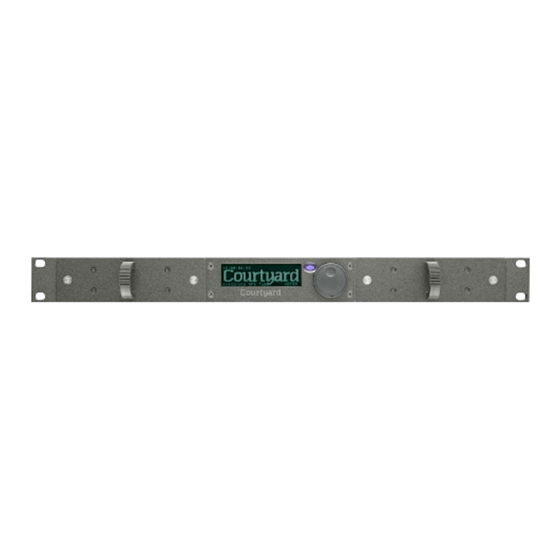
Operating Basics This section outlines the basics of operating the CY460 Sync Pulse and Test Pattern Generator. The information is divided into the following sub-sections: Front-Panel Controls and Indicators Rear Panel Connectors Operating Basics 2.1 Front Panel Buttons and Indicators Figure 2.1 shows the CY460 Sync Pulse and Test Pattern Generator Front Panel. - Page 42 Menu system completely. You need to press the button a suitable number of times to get back to the stand-by screen (the one with the “Courtyard” logo, one press “up” from the top level Menu) – this will save any changes that you have made to the non-volatile memory.
-
Page 43: Rear Panel Connectors
2.2 Rear Panel Connectors Figure 2.2 shows the CY460 Sync Pulse and Test Pattern Generator Rear Panel. Descriptions of the rear-panel connectors appear on the following pages. In the standard configuration, all connectors are populated except SDI 3, SDI 3 Black, SDI 4 & SDI 4 Black. - Page 44 If the CY460 Sync Pulse and Test Pattern Generator is to be used as a Master reference (i.e. not genlocked), you do not have to supply a signal, and you may leave these BNCs unconnected.
- Page 45 GPS (input with +5v DC output to power antenna) This coaxial connector is used to connect a suitable GPS aerial in order to be able to genlock the CY460 Sync Pulse and Test Pattern Generator, and to provide accurate time and date information.
-
Page 46: Operating Basics
2.3 Operating Basics The CY460 Sync Pulse and Test Pattern Generator unit produces a wide variety of video and audio references and test pattern signals suitable for distribution within a typical television engineering installation. The CY460 Sync Pulse and Test Pattern Generator can be configured in a number of ways: ... -
Page 47: Software Field Upgrade
A power-cycle could be required as part of the data file update – ensure that the unit is not in service during the update process. There are four different files that can be uploaded to the CY460 SPG. Each is loaded at a specific memory address included as part of the filename: Bootware At present, the Bootware file can only be uploaded at the factory. - Page 48 Ensure that the CY460 SPG is ON. On your PC, run the “CourtyardSystemUpdate_v6.0.0.0.exe” program. In the dialog boxes, enter the IP Address and IP Mask to be those of the CY460 SPG. Select the [ Get Device Mode ] button.
- Page 49 More recent versions of the CourtyardSystemUpdate program auto-detect the programming mode of the CY460 SPG. Pressing the [ Get Device Mode ] button will confirm the current “Device Mode”. If the “Device Mode” is not “Bootloader”, when [ Send File To Device ] is pressed, a dialog box is displayed, warning that the CY460 SPG needs to be rebooted and that all outputs will be corrupted.
-
Page 50: Menu System
Menu System The CY460 Sync Pulse and Test Pattern Generator provides the user with a menu interface to control the functions and options of the instrument. 3.1 Menu Screens and Maps The menus can always be viewed on the front panel LCD display, and optionally “in-vision” in an “on-screen-display”... - Page 51 By pressing the rotary control from either of the above screens, you access the Top Level Menu. This menu gives you access to the 5 key menus that are used to control and configure the CY460 SPG: 1. Audio Menu 2.
- Page 52 GPS Report Configuration Network IP Address Subnet Mask Gateway MAC Address NTP Menu DashBoard Backup Device SNMP Option Enable Calibration Figure 3.1 : CY460 SPG – Menu Map (diagrammatic). 28 February 2017 Operation and Maintenance CY460_Operational_Manual_405 Page 52 of 218...
-
Page 53: Audio Menu
3.2 Audio Menu Each video output has audio channels associated with it: SDI 1 has 16 embedded audio channels, SDI Black 1 has 16 embedded audio channels, SDI 2 has 16 embedded audio channels, SDI Black 2 has 16 embedded audio channels, Composite 1 has 16 audio channels in 8 AES pairs, Analog Audio -... - Page 54 Definition for: "AudioChannel = Audio nn" This menu item allows the user to select which audio output they are operating on. The field “AudioChannel” consists of three sub fields. One item from each of the following columns will always appear in the three sub-fields, although not all combinations are valid: SDI1 Pattern Left...
- Page 55 Definition for: "Tone Type xxx" The options in the field “xxx are: 400Hz 800Hz 1KHz Sweep Step A-Maj Chord A-Maj Scale Spot Frequency Sample 1 not available for all channels Sample 2 not available for all channels Sample 3 not available for all channels Sample 4 not available for all channels Sweep ramps the frequency from 20Hz to 20KHz in 3 seconds.
- Page 56 Definition for: "Gain nndB" The options in the field “nndB” are: Silence -60dB..+18dB (in 1dB steps) The upper limit is actually set by the dBFS menu (detailed below). Definition for: "Interrupt xx" The options in the field “xx” are: 1 sec 3 sec Glits Blits...
- Page 57 Definition for: "Sequence xxx" The options in the field “xxx” are: Tone Sample Tone.Sample Squawk Squawk.tone Squawk.sample Squawk.Tone.Sample Squawk.Sample.Tone 28 February 2017 Operation and Maintenance CY460_Operational_Manual_405 Page 57 of 218...
-
Page 58: Video Menu
3.3 Video Menu The Video menu for the SDI 1 and SDI 2 channels appears below: SD-SDI formats HD-SDI formats "Video Channel nn = xx" "Standard nn" "Description...." "Offset 0000000 00.00u " "Offset 0000000 00.000000 " " V= 0000 H=0000 "... - Page 59 The Video menu for the Composite 1 channel appears below: "Video Channel nn = xx" "Standard nn" "Description...." "Offset 000000000 00.00u 000.0°" "Fr= 0 V= 0000 H=0000 Sc= 0000" "Pattern Number nnn" "Description...." "ID Memory n" "Character n/mm = yyy" "Description...."...
- Page 60 Composite 1 output format. Each of the three Tri-Black outputs can be simultaneously outputting formats differing again from those on the pattern outputs. So, the CY460 Sync Pulse and Test Pattern Generator could be configured to provide up to 6 different output formats simultaneously.
- Page 61 nn = "06" : Description = "720x 625/50/i " nn = "07" : Description = "1280x720/60/p " nn = "08" : Description = "1280x720/59.94/p " nn = "09" : Description = "1280x720/50/p " nn = "10" : Description = "1280x720/30/p "...
- Page 62 Definitions for: SD SDI channels: "Offset 0000000 00.00µ " " V= 0000 H=0000 " HD SDI channels: "Offset 0000000 00.000000 " " V= 0000 H=0000 " Composite 1, Black 1, & Tri-Black channels: "Offset 0000000 00.00µ 000.00º" "Fr= 0 V= 0000 H=0000 Sc= 000"...
- Page 63 Pattern lists can be found in Appendix I at the end of this manual. These new patterns can be uploaded to your CY460 SPG over the Ethernet interface. You will need to find some maintenance time to do this as a power cycle may be required.
- Page 64 Definitions for: "ID Memory n" "Character n/mm = yyy" "Description...." This menu triplet allows the user to select and edit the ID Text / Image for the video output they are operating on. ID Text / Image is selectable on: SDI 1 output SDI 2 output Composite 1 output...
- Page 65 Sub-definitions for: "ID Memory n" "-ID Image " "-Description...." When the ID Memory is selected to be an ID Image, the menu appears as above. The options in the field “n” are: “n” = 4 through 64. These are ID Image memories. Each memory is edited individually. “n” selects which memory is ‘active’...
- Page 66 Definition for: "ID Char Size n" This menu item allows the user to select the size of the text in the ID Text box for the video output they are operating on. The options in the field “n” are: “n” = 1 through 7. The number “n”...
- Page 67 Definition for: "ID Visible Rows n" This menu item allows the user to select the rows of ID Text that are to be visible in the ID Text box for the video output they are operating on. The options in the field “n” are: 1 &...
- Page 68 Definition for: "ID Row Motion Static" This menu item allows the user to control the animation of the text rows within the ID Text box for the video output they are operating on. These animated modes can be useful to indicate the video output is ‘live’.
- Page 69 Definition for: "Pattern Bounce Off" This menu item allows the user to control the Bounce animation on applicable patterns. Not all patterns bounce. Bounce is a useful test as it dynamically changes the average picture level (APL) of the pattern. This can be used to help diagnose errors in downstream video equipment.
- Page 70 Definition for: "Circle Type Off" This menu item allows the user to enable the circle feature on the Pattern video output they are operating on. For the Composite 1 output, the menu line appears as: "Circle Type Off" The options in the field “Off” are: Static Animated Animated circles are useful as a lip-sync test as the circle and audio are synchronised...
- Page 71 Definition for: "OSD Time & Date xx" This menu item allows the user to control the behaviour of the ‘on screen display’ (OSD) when it is not being used for menus. The options in the field “xx” are: Time Date Time-Date When “on”...
- Page 72 Definition for: "Number Of OSDRows= 6" This menu item allows the user to select the number of rows of text in the OSD menus. This is currently fixed at 6 rows. Definition for: "Event Warnings Off" This menu item allows the user to control the behaviour of the LCD when an “event” occurs. The options in the field “Off”...
- Page 73 Definitions for: "Pattern ToneSil Tone" "Black ToneSil Tone" These menu items allow the user to control the audio content of the audio embedders on the SDI Pattern and SDI Black video output signals. The options in the fields “Tone” are: Tone Audio is embedded as configured in the associated Audio menus.
- Page 74 Definitions for: “Pattern EDH On” “Black On” These menu items allow the user to control whether EDH (Error Detection and Handling) data is included on the SD-SDI Pattern and SD-SDI Black video output signals. The options in the field “On” are: No EDH data added to the SDI output.
- Page 75 Definitions for: "Pattern F1L7 On" (“Pattern F1L10” for NTSC) "Black F1L7 On" (“Black F1L10” for NTSC) These menu items allow the user to control whether the F1L7 (Field 1 Line 7) or F1L10 (field 1 Line 10) ident signals appear on the Composite 1, Black 1 and Tri-Black video output signals.
-
Page 76: Timecode Menu
See Figure 1.2d : CY460 SPG – Timecode in Section 1.2 : Functional Diagrams for a functional diagram of the CY460 Timecode system. See Figure 3.2 : CY460 SPG – Setting Time and Date Parameters at the end of this section for a flowchart outlining the procedure to initially set your local time and date parameters. - Page 77 The Timecode menu for all the Video timecodes appears below: "Description...." "Format Fixed by Video " "Running Time = hh:mm:ss:ff" "Offset = SPGTime + 00:00:00:00" " " "USERBITS " The Timecode menu for all the LTC timecodes appears below: "Description...." "Format "...
- Page 78 The Timecode menu for Analog Ref VITC appears below: " Analog Ref VITC" " " "VITC Ref Time hh:mm:ss:ff" "Locked – PAL VITC on line = nn" " " "Locked to Video + VITC " The Timecode menus for Summer DST Event, Winter DST Event and Leap Second Event are very similar –...
- Page 79 Definition for: "Description...." The options that appear in this menu line are: “SDI 1 & SDIBlack 1 Timecode” for SDI and SDI Black 1 output “SDI 2 & SDIBlack 2 Timecode” for SDI and SDI Black 2 output “Composite 1 Timecode” for Composite 1 output “Black 1 Timecode”...
- Page 80 Definition for: "Format " This menu item allows the user to select the required format for the LTC output they are operating on. The options in the field “nnx” for the LTC channels are limited to: “nnx” = " 30p" “nnx”...
- Page 81 Definition for: "Offset = UTC + 00:00:00:00" This menu item allows the user to offset SPG Time with respect to UTC Time. This is where the user should enter their current time-zone offset from UTC. This offset should not include any daylight saving offset that may be in force – Daylight Saving adjustments are handled separately (see below).
- Page 82 Definition for: "Nudge = 00:00:00:00" This menu item allows the user to manually adjust UTC Time (where the SPG is not synchronised to an external time source, such as GPS or NTP, i.e. when neither option is enabled in the “Option Enable” menu). The field “00:00:00:00”...
- Page 83 Definition for: "Leap Second Off" The options in this menu line are: User Defined If set to “User Defined”, then the time and date will automatically adjust at the time and date set in the Leap Second Event (UTC) menu. Definition for: "Action DateTime = hh:mm:ss:ff"...
- Page 84 Even if you don’t implement DST, it is still useful to enter your country code, as this informs the CY460 SPG of its location in either the Northern or Southern hemisphere. The menus adjust to the location information. The “Country Code” and “State Code” definitions are detailed below.
- Page 85 "Description...." This menu pair allows the user to set the geographical State Code of the CY460 SPG, but they only appear in the menu when the preceding menu option regarding “Country Code” is set for a country that has multiple states defined as having differing Daylight Saving criteria.
- Page 86 "xLocked to GPS " If the CY460 SPG is set for a Genlock Mode other than one of the GPS options, the following menu is displayed. The current time and date are displayed as received from GPS. The last line of the menu reports that the selected Genlock Mode is not associated with the GPS system..
- Page 87 "tLocked to NTP " If the CY460 SPG is set for a Genlock Mode other than NTP, the following menu is displayed. The current time and date are displayed as received from NTP. The last line of the menu reports that the selected Genlock Mode is not associated with the NTP system.
- Page 88 "Locked – PAL VITC on line = nn" This menu line reports that the CY460 SPG is genlocked to the external Video Reference, the format of the external Video Reference, and the line on which valid VITC data is present.
- Page 89 Definition for: "Locked to Video + VITC " This menu line reports the Lock Status relating to the external Video Reference when it includes a valid VITC signal. This menu line appears at the end of a successful genlocking sequence. When an external Video Reference is not present, the following menu line appears: "Genlock ERROR --- No Video Ref"...
- Page 90 Additional Information for the Summer DST Event (UTC) and Winter DST Event (UTC) menus If the menu line “Daylight Saving” in the UTC DateTime menu is set to “User Defined”, the time and date fields of these menus can be edited. If the menu line “Daylight Saving” is set to Off, editing is disabled.
- Page 91 Leap Second is to be added. For this reason it is not possible for all versions of the CY460 SPG software to have the time and date of the next event coded into the software. Historically the Earth’s spin is slowing down but some scientists think that global warming may make the Earths spin increase.
- Page 92 Leap Seconds have been added since 1972: Year Jun 30 Dec 31 Year Jun 30 Dec 31 Year Jun 30 Dec 31 1971 ---- ---- 1987 2003 1972 1988 2004 1973 1989 2005 1974 1990 2006 1975 1991 2007 1976 1992 2008 1977...
- Page 93 = -5 hrs for New York (Eastern Standard Time). Exit Menu CY460 SPG Time / Date Settings Finish 14 Nov, 2013 Figure 3.2 : CY460 SPG – Setting Time and Date Parameters 28 February 2017 Operation and Maintenance CY460_Operational_Manual_405 Page 93 of 218...
- Page 94 ISO 3166-1 Country Code list English short name Alpha-2 code Alpha-3 code Numeric code ISO 3166-2 codes ISO 3166-2:AF Afghanistan ISO 3166-2:AX Åland Islands ISO 3166-2:AL Albania ISO 3166-2:DZ Algeria American Samoa ISO 3166-2:AS ISO 3166-2:AD Andorra ISO 3166-2:AO Angola Anguilla ISO 3166-2:AI Antarctica...
- Page 95 Christmas Island ISO 3166-2:CX Cocos (Keeling) Islands ISO 3166-2:CC ISO 3166-2:CO Colombia ISO 3166-2:KM Comoros ISO 3166-2:CG Congo ISO 3166-2:CD Congo, the Democratic Republic of the Cook Islands ISO 3166-2:CK ISO 3166-2:CR Costa Rica ISO 3166-2:CI Côte d'Ivoire Croatia ISO 3166-2:HR Cuba ISO 3166-2:CU ISO 3166-2:CW...
- Page 96 ISO 3166-2:HT Haiti Heard Island and McDonald Islands ISO 3166-2:HM ISO 3166-2:VA Holy See (Vatican City State) Honduras ISO 3166-2:HN ISO 3166-2:HK Hong Kong Hungary ISO 3166-2:HU ISO 3166-2:IS Iceland ISO 3166-2:IN India ISO 3166-2:ID Indonesia ISO 3166-2:IR Iran, Islamic Republic of ISO 3166-2:IQ Iraq Ireland...
- Page 97 ISO 3166-2:FM Micronesia, Federated States of Moldova, Republic of ISO 3166-2:MD ISO 3166-2:MC Monaco Mongolia ISO 3166-2:MN Montenegro ISO 3166-2:ME Montserrat ISO 3166-2:MS ISO 3166-2:MA Morocco ISO 3166-2:MZ Mozambique ISO 3166-2:MM Myanmar ISO 3166-2:NA Namibia Nauru ISO 3166-2:NR ISO 3166-2:NP Nepal ISO 3166-2:NL Netherlands...
- Page 98 Sao Tome and Principe ISO 3166-2:ST ISO 3166-2:SA Saudi Arabia ISO 3166-2:SN Senegal ISO 3166-2:RS Serbia Seychelles ISO 3166-2:SC ISO 3166-2:SL Sierra Leone ISO 3166-2:SG Singapore ISO 3166-2:SX Sint Maarten (Dutch part) ISO 3166-2:SK Slovakia Slovenia ISO 3166-2:SI Solomon Islands ISO 3166-2:SB ISO 3166-2:SO Somalia...
- Page 99 ISO 3166-2:VI Virgin Islands, U.S. ISO 3166-2:WF Wallis and Futuna Western Sahara ISO 3166-2:EH ISO 3166-2:YE Yemen ISO 3166-2:ZM Zambia Zimbabwe ISO 3166-2:ZW We will endeavour to keep this list updated in future versions of the software. 28 February 2017 Operation and Maintenance CY460_Operational_Manual_405 Page 99 of 218...
- Page 100 Currently the CY460 SPG supports three countries with subdivisions. These are Australia, Canada and USA. We will add more state codes in future versions of software. Listed below are details relating to the ISO 3166-2 State Codes of countries supported by the CY460 SPG.
- Page 101 Canada: Map of Canada with each territory labelled with the second part of its ISO 3166-2 code. SPG Offset Daylight Saving Code Subdivision name (en) Subdivision name (fr) CA-AB Alberta Alberta CA-BC Colombie-Britannique British Columbia CA-MB Manitoba Manitoba CA-NB Nouveau-Brunswick New Brunswick CA-NL Newfoundland and Labrador...
- Page 102 China: Code Subdivision name SPG Offset Daylight Saving CN-11 Beijing CN-50 Chongqing CN-31 Shanghai CN-12 Tianjin CN-34 Anhui CN-35 Fujian CN-62 Gansu CN-44 Guangdong CN-52 Guizhou CN-46 Hainan CN-13 Hebei CN-23 Heilongjiang CN-41 Henan CN-42 Hubei CN-43 Hunan CN-32 Jiangsu CN-36 Jiangxi CN-22...
- Page 103 Russia: Code Subdivision name 1 SPG Offset Daylight Saving RU-AD Adygeya, Respublika RU-AL Altay, Respublika RU-BA Bashkortostan, Respublika RU-BU Buryatiya, Respublika RU-CE Chechenskaya Respublika RU-CU Chuvashskaya Respublika RU-DA Dagestan, Respublika RU-IN Ingushetiya, Respublika RU-KB Kabardino-Balkarskaya Respublika RU-KL Kalmykiya, Respublika Karachayevo-Cherkesskaya RU-KC Respublika RU-KR...
- Page 104 RU-KEM Kemerovskaya RU-KIR Kirovskaya RU-KOS Kostromskaya RU-KGN Kurganskaya RU-KRS Kurskaya RU-LEN Leningradskaya RU-LIP Lipetskaya RU-MAG Magadanskaya RU-MOS Moskovskaya RU-MUR Murmanskaya RU-NIZ Nizhegorodskaya RU-NGR Novgorodskaya RU-NVS Novosibirskaya RU-OMS Omskaya RU-ORE Orenburgskaya RU-ORL Orlovskaya RU-PNZ Penzenskaya RU-PSK Pskovskaya RU-ROS Rostovskaya RU-RYA Ryazanskaya RU-SAK Sakhalinskaya RU-SAM...
- Page 105 USA: Map of the United States with each state and the District of Columbia labelled with the second part of its ISO 3166-2 code. Code Subdivision name SPG Offset Daylight Saving US-AL Alabama US-AK Alaska US-AZ Arizona US-AR Arkansas US-CA California US-CO Colorado...
- Page 106 US-NM New Mexico US-NY New York US-NC North Carolina US-ND North Dakota US-OH Ohio US-OK Oklahoma US-OR Oregon US-PA Pennsylvania US-RI Rhode Island US-SC South Carolina US-SD South Dakota US-TN Tennessee US-TX Texas US-UT Utah US-VT Vermont US-VA Virginia US-WA Washington US-WV West Virginia...
-
Page 107: Genlock Menu
In a third mode the CY460 SPG can frequency lock to a reference from an external oscillator. Again, in this mode, the long term stability is defined by the external oscillator. - Page 108 Generator Generator Generator Generator Generator CY460 SPG Functional Diagram - Genlock 4 Dec, 2013 Figure 3.3 : CY460 – Genlock to External Video Reference. The Genlock Menu appears below: "Lock Mode xxx" "Unlock Mode xxx" "-Lock Status = xxx" "-Ref Signal = xxx"...
- Page 109 Definitions for: "Lock Mode = xxx" This menu line allows the user to select the required genlock mode of the CY460 SPG. The options in the field “xxx” are: Internal Lock Lock to the internal 10MHz oscillator. Genlock Lock to an external CVBS Video signal.
- Page 110 “Locked” is displayed when the CY460 SPG has successfully genlocked to the external genlock video reference. “Locked to 10MHz” is displayed while the CY460 SPG has locked to the external 10MHz frequency reference. Additional options will appear in this field, mirroring a subset of the field options detailed in the following definitions.
- Page 111 59.94i " "1080 " While the CY460 SPG is actively evaluating the external reference format, an additional option will appear in this field. This option appears as: “ Unknown format” The following genlock reference formats are not supported by the CY460 SPG: "1080...
- Page 112 GPS signal. “xLocked to GPS” (where x = t, i, a or p) is displayed when the CY460 SPG has successfully locked to the pre-selected mode of GPS Locking (the display progresses...
- Page 113 “Searching VITC” appears while the CY460 SPG is searching for a valid VITC signal. “VITC found” appears briefly when the CY460 SPG has found a valid VITC signal. “Locking to VITC” appears while the CY460 SPG is actively genlocking to the VITC signal.
-
Page 114: System Setup Menu
When the GPS option is not installed/enabled, the “GPS Report” line appears as: "-GPS..Option not enabled" The System Setup Menu provides a gateway to the less frequently used options in the CY460 SPG. These options include: Extended information in the form of reports,... - Page 115 These menu lines report the power cycle counts and “in service” times for both of the PSUs installed in the N+1 Dual Redundant PSU CY460D SPG. When there is only one PSU, as in the single PSU variant of the frame, the CY460 SPG, these menu lines appear as: "PSU turned on nnnnnn times...
-
Page 116: Event Report
" "23.59.59.999 12 September 2012" The Event Report provides access to the last 99 events recorded by the CY460 SPG. These events may relate to normal expected functionality or to systemic errors. This information might be useful in monitoring and diagnosing a system problem outside the CY460 SPG, or a reliability problem within the CY460 SPG. - Page 117 EventNewMaxTemp0 EventNewMaxTemp1 EventNewMaxTemp2 EventNewMaxTemp3 EventNewMaxTemp4 EventNewMaxTemp5 EventNewMaxTemp6 EventNewMaxTemp7 EventNewMaxTempAlarm0 EventNewMaxTempAlarm1 EventNewMaxTempAlarm2 EventNewMaxTempAlarm3 EventNewMaxTempAlarm4 EventNewMaxTempAlarm5 EventNewMaxTempAlarm6 EventNewMaxTempAlarm7 EventNewMinTemp0 EventNewMinTemp1 EventNewMinTemp2 EventNewMinTemp3 EventNewMinTemp4 EventNewMinTemp5 EventNewMinTemp6 EventNewMinTemp7 EventNewMinTempAlarm0 EventNewMinTempAlarm1 EventNewMinTempAlarm2 EventNewMinTempAlarm3 EventNewMinTempAlarm4 EventNewMinTempAlarm5 EventNewMinTempAlarm6 EventNewMinTempAlarm7 EventEthernetLinkMade EventEthernetLinkLost EventGPSSetTimecodeFromGPSFlag EventGPSUnSetTimecodeFromGPSFlag 28 February 2017 Operation and Maintenance CY460_Operational_Manual_405 Page 117 of 218...
-
Page 118: System Report
Definition for: "CY460 SPG xxx.xxx.xxx.xxx" This menu line reports the user programmed Ethernet IP Address of the CY460 SPG (see “Network Menu” below for user configuration details). The options in the sub-fields “xxx” appear as: “xxx” = 0 through 255 Definition for: "Ethernet... - Page 119 Definition for: "ArmFile_0x00200000_vxx_xxx.ata" The Arm File menu line is in the form: "ArmFile_0x00200000_vxx_xxx.ata". The sub-field “0x00200000” is the load address. The sub-field “vxx_xxx” is the version number. Updates of this file may be uploaded via the Ethernet interface using the procedure outlined in Section 2.4 : Software Field Upgrade.
- Page 120 Definition for: "LogFile --------- none present" This menu line reports whether there is a user-uploaded Bitmap Logo file stored in the CY460 SPG. If the Bitmap Logo file is absent or empty, the menu line appears as above. If there is a valid Bitmap Logo file present, this menu line appears as: "LogFile_0x38000000__xx_xx_.ata"...
- Page 121 The “Bootware vxxxxx” field indicates the bootware version in use. This is not usually modified by field upgrades as it relates to the motherboard bootware components in the CY460 SPG. The “Software vxxxxx” field indicates the software version in use. This can be modified in...
-
Page 122: Gps Report
GPS option has been installed and enabled. The CY460 SPG GPS system is currently capable of detecting satellites from both the American GPS (Global Positioning System) and the Russian GLONASS (GLObal NAvigation Satellite System) systems. - Page 123 Definitions for: "Pxx SV = mm SNR = nn " "Lxx SV = mm " The menu lines starting with “P” and “L” represent which satellite system is being referred to: for the American GPS system for the Russian GLONASS system The first sub-field “xx”...
-
Page 124: Configuration Menu
The Configuration Menu provides access to a range of features that determine the functionality of the CY460 SPG not otherwise covered by other menu settings. These options are typically set up during the system commissioning of the CY460 SPG, and thereafter are unlikely to be changed. - Page 125 Definition for: "LCD Flash on Error xxx" This menu row allows the user to select the LCD and Button to Flash or not when an error is reported. The options are: No Flash LCD & Select Button Flash when errors are reported Definition for: "LCD Animation xxx"...
- Page 126 Definition for: "AES1-8 + Analog = Composite1" This menu item allows the user to select the appropriate video from which the AES and Analog Audio are referenced. This is usually only relevant where lip-sync test pattern elements are being used. The options are: SDI1 SDI2...
- Page 127 Definition for: "10MHz Mode= xxx" The CY460 SPG can lock to an external 10MHz reference. This reference can be sine, square or pseudo-sine. It is passed to the CY460 SPG main module via the multifunction sub- module. The CY460 SPG generates its own 10MHz with pseudo-sine wave output.
-
Page 128: Network Menu
Definition for: "IP Address 000.000.000.000" This menu line allows the user to enter the pre-determined IP address of the CY460 SPG. The options in the sub-fields “000” are: 000 through 255. “000” is the default “no action” setting. - Page 129 000.000.000.000" This menu line allows the user to enter the pre-determined Gateway address of the CY460 SPG. Typically, this might be the IP address of a network hub to which the CY460 SPG is connected. The options in the sub-fields “000” are: 000 through 255.
-
Page 130: Ntp Menu
"The NTP system is off" This menu line allows to user to control whether the CY460 SPG is configured to be an NTP Client or NTP Server, or whether the NTP System is Off. The options in this menu line appear as: "The NTP system is... - Page 131 Sub-definition for: "Poll Server every 240 secs" This menu line allows the user to set the interval (in seconds) at which the CY460 SPG requests NTP time information from the specified time server. The options in the sub-field “240” are:...
- Page 132 " Sub-Definition for: "Serve NTP if 'No GPS'?..xxx" This menu line determines whether the CY460 SPG will serve NTP requests when the GPS option is either not enabled or is not locked. The options in the sub-field “xxx” are: NTP Server will not reply to NTP requests while GPS is disabled.
- Page 133 Sub-Definition for: "Serve NTP if 'SPG Failed'?.xxx" This menu line determines whether the CY460 SPG will serve NTP requests while an accompanying Changeover unit has detected an error on the unit. The options in the sub-field “xxx” are: NTP Server will not reply to NTP requests while the SPG has ‘failed’.
-
Page 134: Dashboard Menu
PC-based Remote Control Program. Definition for: "Port nnnn" This menu line allows the user to set the Ethernet Port through which the CY460 SPG communicates with the external PC-based Remote Control Program. The options in the sub-field “nnnn” are: 5253... - Page 135 Definitions for: "Character mm = yyy" "DashBoard Password = Alpha----" These menu lines only appear when the “Connection URM” menu line is set for “Managed”. This menu doublet allows the user to select and edit the Dashboard password. The options in the field “mm” are: “mm”...
-
Page 136: Backup Device Menu
"Poll is disabled...." "This is PRIMARY..so never poll" " " The Backup Device Menu is only used when the CY460 SPG is set to be the Backup unit in a Changeover pair. Definition for: "Poll the Primary SPG on.."... - Page 137 Definition for: "Poll is disabled...." This menu line appears if the CY460 SPG is set as the Primary unit in a Changeover pair. It informs the user that the CY460 SPG is the Primary unit of a Changeover pair, and consequently, polling (of the remote device) is disabled.
-
Page 138: Option Enable Menu
Every time the CY460 is powered up, this entry displays a pseudo-randomly generated 13- character key. This menu item cannot be changed by the user. This key is unique to each CY460 SPG, and should be quoted when requesting any additional Option Enable Keys. - Page 139 Definitions for: "TB xxxx-xxxx-xxxx" "HD Enable? No 0000:0000:0000" "3G Enable? No 0000:0000:0000" "GPS Enable? No 0000:0000:0000" "NTP Enable? No 0000:0000:0000" These menu lines allow the user to either view the Option Keys, or to input supplied Option Update Key(s) in order to enable the related option(s). Updates can be performed “live” – there is usually no requirement to re-boot or re-power the unit after key entry.
-
Page 140: Calibration Menu
IMPORTANT The Calibration Menu contains fundamental settings relating to the functionality and accuracy of the CY460 SPG. These settings are programmed during initial testing, configuration and alignment. Under normal circumstances, it should not be necessary to adjust any of these settings after the unit has been installed. - Page 141 When the CY460 SPG is configured for “Internal Lock” (see Section 3.5 : Genlock Menu), the video outputs on the CY460 SPG will “free run” compared to an external video signal from a known reference. To set the 10MHz oscillator, view both the Composite output and the known reference on a vectorscope.
- Page 142 382-390. Disclaimer Courtyard retains a record of the calibration settings for each CY460 SPG that leaves the factory. Most of these settings are determined during initial testing, configuration and alignment. They should not normally require adjustment or reconfiguration during service.
- Page 143 These calibration values are obtained during initial testing using a DVM to measure pre- defined DC levels produced by each video channel DAC. The procedure requires that a suitable adapter cable including a 75 termination will be needed to connect the CY460 SPG output BNC to the connector(s) on your DVM.
-
Page 144: Troubleshooting
Troubleshooting Generally speaking, the CY460 SPG is extremely reliable under normal “steady state” operating conditions. If you are having problems, select the symptom from the list below that closely relates to your particular problem, and perform the checks / actions listed. - Page 145 Please contact Courtyard Electronics Limited for further assistance. When you contact Courtyard Electronics Limited regarding an issue on your unit, and so that we can process your enquiry efficiently, you should have available at least one of the following items of information in addition to your personal / company details (name, company, telephone, email): ...
-
Page 146: Warranty
Warranty One Year Limited Warranty Courtyard Electronics Ltd. warrants all models in its CY460 Sync Pulse and Test Pattern Generator range against defects in parts and labour for one year from receipt of the product by the end user. Courtyard Electronics Ltd reserves the right to choose whether to repair or replace defective equipment. -
Page 147: Appendix A : Specifications
temperature, altitude, humidity, and vibration conditions are within the operating limits described in Table A.34. The CY460 Sync Pulse and Test Pattern Generator must have a warm-up period of at least 20 minutes. The CY460 Sync Pulse and Test Pattern Generator must have been calibrated and adjusted at ... - Page 148 Table A.1 : Video Reference Inputs Characteristic Performance Requirement Reference Information Input connector type 2 x 75Ω BNC (loop through) Input Return loss > 30dB to 10MHz Inputs NTSC Black Burst 525 Sync PAL Black Burst 625 Sync Tri-Level Sync Input requirements Amplitude -6 dB to +6 dB...
- Page 149 Table A.2 : Frequency Reference Inputs Characteristic Performance Requirement Reference Information Input connector type 1 x 50Ω BNC (terminating) Input Return loss > 30dB to 10MHz Inputs 10 MHz continuous wave Input requirements Amplitude 1 Vp-p (nominal); For 1 Vp-p input, Signal 2.5 Vp-p (maximum).
- Page 150 Table A.4 : Frequency Reference Outputs Characteristic Performance Requirement Reference Information Output connector type 1 x BNC Output impedance and 50Ω required termination Signal amplitude 1.0 V ± 10% Rise and fall time 5ns > Rise /Fall < 44ns 10% to 90% Jitter Typically 2ns Outputs...
- Page 151 Table A.6 : Analog Video Outputs Characteristic Performance Requirement Reference Information Output connector type 75Ω BNC Number of outputs Composite Pattern Output on 2 BNCs 10 BNCs in total Composite Black Burst Output on 2 BNCs Tri-Black 2 Output on 2 BNCs Tri-Black 3 Output on 2 BNCs Tri-Black 4 Output on 2 BNCs Output impedance...
- Page 152 Notes: Field blanking Composite output NTSM-M, NTSC-J Field 1 lines 1 – 20 inclusive are blanked, i.e. there is no pattern information, but there may be VITC etc. Field 2 lines 263 – 283 inclusive are blanked, i.e. there is no pattern information, but there ...
- Page 153 Table A.7 : Serial Digital Interface Characteristic Performance Requirement Reference Information Output connector type 75Ω BNC Number of outputs SDI 1 Pattern Output on 2 BNCs. 8 BNCs in total SDI 1 Black Output on 2 BNCs. SDI 2 Pattern Output on 2 BNCs. SDI 2 Black Output on 2 BNCs.
- Page 154 Table A.7 : Serial Digital Interface (continued) Characteristic Performance Requirement Reference Information Monochrome bitmap logo or Maximum 30 character in each of 3 rows Animation effects ID Text Gray scale 4 level Full color bitmap logo Any size up to full frame. Keyed over test pattern Embedded audio 270Mbps...
- Page 155 Picture A.1 : CY460 SPG – 270Mbps Eye and Jitter Picture A.2 : CY460 SPG – 1.5Gbps Eye and Jitter Picture A.3 : CY460 SPG – 3Gbps Eye and Jitter 28 February 2017 Appendices CY460_Operational_Manual_405 Page 155 of 218...
- Page 156 Table A.8 : AES/EBU Audio Unbalanced Outputs Characteristic Performance Requirement Reference Information Output connector type 3 x BNC Number of outputs 2 x unbalanced Audio on BNC AES-3 AES-3id 1 x unbalanced DARS on BNC AES-11 DARS is indicated as “non- PCM audio”...
- Page 157 Table A.9 : AES/EBU Audio Balanced Outputs Characteristic Performance Requirement Reference Information Output connector type Molex Micro Clasp 2mm 30 pin Shared with Analog Audio Part Number 0512423000 and LTC Number of outputs 8 x Balanced Audio AES-3 1x DARS AES-11 DARS is indicated as “non- PCM audio”...
- Page 158 Table A.11 : Analog Audio Outputs Characteristic Performance Requirement Reference Information Output connector type Molex Micro Clasp 2mm 30 pin Shared with AES/EBU Part Number 0512423000 Audio and LTC Number of outputs 2 x Balanced 1 x Stereo balanced pair Output impedance 50Ω...
- Page 159 Table A.12 : Programmable Pulse Unbalanced Outputs Characteristic Performance Requirement Reference Information Output connector type 3 x BNC Output impedance and 75Ω required termination Signal amplitude 3.3V ± 10% CMOS compatible Rise and fall time 5ns > Rise /Fall < 44ns 10% to 90% Jitter Typically 2ns...
- Page 160 Table A.13 : GPI (General Purpose Interface) Characteristic Performance Requirement Reference Information Connector type Molex Micro Clasp 2mm 10 pin Shared with RS232 and Part Number 0512421000 ONAIR Outputs Pin 7: GP output 1 Open Collector Pin 8: GP output 2 Open Collector Pin 1: GND Pin 10: GND Output level...
- Page 161 Table A.21 : Ethernet Interface Characteristic Performance Requirement Reference Information Connector type 1 x RJ45 - 8P8C IEEE Standards Compliance IEEE 802.3i-1990 10BASE-T IEEE 802.3u-1995 100BASE-TX IEEE 1588-2008 Precision Time Protocol IEEE RFC Compliance IP over Ethernet 1027 Proxy ARP 1157 SNMP 1377...
- Page 162 Fuse 5mm x 20mm IEC 60127-2 Antisurge 2A 250V Fuse identification marking T2A H250V Operational AC current CY460 < 130mA @ 230 VAC Single PSU < 210mA @ 120 VAC CY460D < 130mA @ 230 VAC Dual N+1 PSU <...
- Page 163 Information Dimensions Height 43.5 mm (1.71 in) Width 482.5 mm (19.00 in) Depth 405 mm (15.95 in) CY460 5.10 kg Single PSU SPG (11.3 lbs) Net Weight CY460 5.85 kg Single PSU SPG (12.9 lbs) Net Weight Shipping box Height...
- Page 164 Table A.34 : Environment characteristics Characteristic Performance Requirement Reference Information Temperature Operating 0 °C to +40 °C Non operating -20 °C to +60 °C Relative humidity Operating 20% to 80% relative humidity (% RH) at up to +40 °C, non-condensing Non operating 5% to 90% relative humidity (% RH) at up to...
- Page 165 Certifications and Compliances: Table A.35 : Certifications and Compliances Category Standards or Description EC Declaration of Meets the intent of Directive 89/336/EEC for Electromagnetic Compatibility. Conformity-EMC Compliance was demonstrated to the following specifications as listed in the Official Journal of the European Communities : EN55103 Product family standard for audio, video, audio-visual and entertainment lighting control apparatus for professional use.
- Page 166 Table A.35: Certifications and Compliances (continued) Category Standards or Description Pollution Degree A measure of the contaminates that could occur in the environment around and within a product. Typically the internal environment inside a product is considered to be the same as the external. Products should be used only in the environment for which they are rated.
-
Page 167: Appendix B : Connector Pinouts
Appendix B: Connector Pin-outs This appendix lists the pin-outs of various multi-way connectors available on the rear panel of the CY460 Sync Pulse and Test Pattern Generator unit. BALANCED AUDIO / AES / LTC Connector Table B.1: BALANCED Connector pin-out. - Page 168 GPI / RS232 Connector Table B.2: GPI/RS232 Connector pin-out Pin number Signal / Function Ground Ground RS232 - RX RS232 - TX GP Input 1 - TTL compatible GP Input 2 - TTL compatible GP Output 1 - Open Collector GP Output 2 - Open Collector ON-AIR - Open collector Ground...
- Page 169 Pin views of chassis connectors Pin views of mating connectors Mating Connector Part No. : 51353-3000 Mating Connector Part No. : 51353-1000 CY460 SPG Crimp Terminals are : Molex Part No. 56134-9100. MicroClasp connectors - Pinouts Connectors are : Molex MicroClasp 2mm series.
- Page 170 CD405 Breakout Option modules When the CD405 Breakout Option modules are used, they are connected to the CY460 Sync Pulse and Test Pattern Generator unit using multi-way cables. Picture B.2 : Molex Micro-Clasp Breakout Option Cable Assemblies There are two modules – a Molex 10-way to D9, and a Molex 30-way to 2 x D25.
- Page 171 Picture B.4a : CD405 Breakout Option Modules – Typical Mounting (1) Picture B.4b : CD405 Breakout Option Modules – Typical Mounting (2) When the CD405 Breakout Option modules are used, the following connector schedules apply : Table B.4 : Breakout Option – D9 Connector pin-out – P306 Pin number Signal / Function Ground...
- Page 172 Table B.5 : Breakout Option – D25 Connector pin-out – P301 Pin number Signal / Function LTC2 + Ground 0V LTC1 - LTC4 + Ground 0V LTC3 - Ground 0V Ground 0V Ground 0V AES6 + Ground 0V AES5 - Ground 0V LTC2 - LTC1 +...
- Page 173 AUD2 - Ground 0V AES4 - AES3 + Ground 0V AES2 - AES1 + Ground 0V DARS - Ground 0V Ground 0V AUD1 - AUD2 + Ground 0VA Type : 25-pin connector, D-Type, Socket (female). 28 February 2017 Appendices CY460_Operational_Manual_405 Page 173 of 218...
-
Page 174: Appendix D : Rack Mounting
Appendix D : Rack Mounting This appendix provides instructions for installing the CY460 Sync Pulse and Test Pattern Generator into a standard 19-inch equipment rack. Minimum Tool and Equipment List The following tools are required to install the rack mounting hardware into the equipment rack. All tools are standard tools that are readily available. -
Page 175: Installation Instructions
Installation Instructions This procedure describes how to assemble and install the slide-out tracks in the equipment rack, and then how to install the instrument into the rack. Assembling the Slide-out Tracks 1. Identify the equipment rack right verses left slide-out track assemblies by finding the date code label on each assembly. -
Page 176: Appendix E : User Maintenance
Appendix E : User Maintenance This appendix contains procedures for cleaning and performing preventive maintenance on the CY460 Sync Pulse and Test Pattern Generator. General Care Protect the instrument from adverse conditions, i.e. high humidity, high temperatures, etc. The instrument is NOT waterproof. -
Page 177: Preventive Maintenance
“clean room” environment. Servicing The CY460 Sync Pulse and Test Pattern Generator unit should require little or no in-service maintenance to the installed electronics. Provided the measures outlined in the Preventative Maintenance paragraph above are adhered to, the product should perform for several years without any major user intervention. -
Page 178: Important Information
“wash-in” grease and dust, which could severely reduce the conductivity of the component parts. Therefore, Courtyard Electronics Ltd does not recommend the use of these Switch Cleaner products on their equipment, and will not be held liable for any fault caused by inadvertent or unqualified use or application of such products. -
Page 179: Appendix F : Circuit Description
Appendix F : Circuit Description Circuit Description Power Supply section The main board is supplied with +12V from an AC-DC system via a 4-pin Molex connector. The AC-DC system is normally a single Switched Mode Power Supply Unit (SMPSU); alternatively, a dual redundant N+1 SMPSU option is available. -
Page 180: Clock Oscillator Section
Additional external memory consists of: 1G-bit of Flash organised as 1024 sectors each 64K x 16-bit word 16M-bit SRAM organised as 1M x 16-bit word Peripherals and I/O interfaces are supplied: 1 off I C master 1 off USB master for Flash disk connection 1 off RS232 for remote control ... -
Page 181: Sdi Video Output Section
Master Oscillator. The 10MHz master oscillator around X210 provides stability better than 0.22ppm (1Hz) at subcarrier frequency, and allows the CY460 to comply with the System I standard for frequency stability. The master oscillator frequency can be trimmed by software control, via the calibration menu, to compensate for normal crystal ageing. - Page 182 Subcarrier Lock. The oscillator built around crystals X11 and X12 provides either PAL or NTSC subcarrier frequencies to be compared in Burst Phase detector U103A with reference burst (genlock mode) or the master oscillator (free-run mode). In free run mode, U102A is always closed and loop filter U107A is always connected to the phase detector.
-
Page 183: Appendix G : Characters Available For Use In Idents
Appendix G : Characters Available For Use In Idents Characters in Idents come from an intersection list of the first 256 characters from Unicode and the allowable characters in XML 1.1. http://www.w3.org/TR/xml11/#charsets Note: Document authors are encouraged to avoid "compatibility characters", as defined in Unicode [Unicode]. - Page 184 28 February 2017 Appendices CY460_Operational_Manual_405 Page 184 of 218...
- Page 185 28 February 2017 Appendices CY460_Operational_Manual_405 Page 185 of 218...
- Page 186 28 February 2017 Appendices CY460_Operational_Manual_405 Page 186 of 218...
- Page 187 28 February 2017 Appendices CY460_Operational_Manual_405 Page 187 of 218...
- Page 188 28 February 2017 Appendices CY460_Operational_Manual_405 Page 188 of 218...
- Page 189 28 February 2017 Appendices CY460_Operational_Manual_405 Page 189 of 218...
- Page 190 28 February 2017 Appendices CY460_Operational_Manual_405 Page 190 of 218...
- Page 191 28 February 2017 Appendices CY460_Operational_Manual_405 Page 191 of 218...
- Page 192 28 February 2017 Appendices CY460_Operational_Manual_405 Page 192 of 218...
- Page 193 28 February 2017 Appendices CY460_Operational_Manual_405 Page 193 of 218...
-
Page 194: Appendix H : Dc Power Option
When used in conjunction with an AC mains power supply, if the AC mains power is present and within the correct range, the CY460 SPG will be powered from the AC mains and the DC power input will draw less than 100mA. As soon as the AC power is lost or disconnected, a seamless transition to the DC power is accomplished (if the DC power is in the correct range). -
Page 195: Appendix I : List Of Test Patterns
Appendix I : List of Test Patterns The CY460 Sync Pulse and Pattern Generator patterns are stored in a pattern file in FLASH memory. Each signal format has a slightly different set of test patterns.. The pattern file is updateable via the Ethernet interface. - Page 196 List of 625i test Patterns: "black ", //0 "white100 ", //1 "yellow100 ", //2 "cyan100 ", //3 "green100 ", //4 "magenta100 ", //5 "red100 ", //6 "blue100 ", //7 "rp219_000_p2white100_p3Black ", //8 "rp219_001_p2white075_p3Black ", //9 "rp219_002_p2nI_p3Black ", //10 "rp219_003_p2pI_p3pQ ", //11 "16x12hardgrille_blacksquare ", //12 "16x12softgrille_blacksquare...
- Page 197 List of 720p test Patterns: "black ", //0 "white100 ", //1 "yellow100 ", //2 "cyan100 ", //3 "green100 ", //4 "magenta100 ", //5 "red100 ", //6 "blue100 ", //7 "rp219_000_p2white100_p3Black ", //8 "rp219_001_p2white075_p3Black ", //9 "rp219_002_p2nI_p3Black ", //10 "rp219_003_p2pI_p3pQ ", //11 "16x9hardgrille_blacksquare ", //12 "16x9softgrille_blacksquare...
- Page 198 List of 1035i test Patterns: "black ", //0 "white100 ", //1 "yellow100 ", //2 "cyan100 ", //3 "green100 ", //4 "magenta100 ", //5 "red100 ", //6 "blue100 ", //7 "rp219_000_p2white100_p3Black ", //8 "rp219_001_p2white075_p3Black ", //9 "rp219_002_p2nI_p3Black ", //10 "rp219_003_p2pI_p3pQ ", //11 "16x9hardgrille_blacksquare ", //12 "16x9softgrille_blacksquare...
- Page 199 List of 1080i and 1080PsF test Patterns: "black ", //0 "white100 ", //1 "yellow100 ", //2 "cyan100 ", //3 "green100 ", //4 "magenta100 ", //5 "red100 ", //6 "blue100 ", //7 "rp219_000_p2white100_p3Black ", //8 "rp219_001_p2white075_p3Black ", //9 "rp219_002_p2nI_p3Black ", //10 "rp219_003_p2pI_p3pQ ", //11 "16x9hardgrille_blacksquare...
- Page 200 List of 1080p test Patterns: "black ", //0 "white100 ", //1 "yellow100 ", //2 "cyan100 ", //3 "green100 ", //4 "magenta100 ", //5 "red100 ", //6 "blue100 ", //7 "rp219_000_p2white100_p3Black ", //8 "rp219_001_p2white075_p3Black ", //9 "rp219_002_p2nI_p3Black ", //10 "rp219_003_p2pI_p3pQ ", //11 "16x9hardgrille_blacksquare ", //12 "16x9softgrille_blacksquare...
-
Page 201: Appendix J : Connecting To Dashboard
DashBoard can be downloaded from: http://www.rossvideo.com/control-systems/dashboard/products/dashboard.html#download The CY460 Sync Pulse and Test Pattern Generator is always configured as a fixed IPv4 device using the menu system accessible on the front panel. The menu structure is -System Setup Menu > Network Menu. - Page 202 If the ping fails, then the network route is not available. This indicates a basic network architecture failure. Consult a network expert. If the ping is successful, then a DashBoard connection should be possible. 28 February 2017 Appendices CY460_Operational_Manual_405 Page 202 of 218...
-
Page 203: Connecting To Dashboard
Connecting to DashBoard 1. Start the DashBoard application and select “Add New Connection” 2. Select “TCP/IP openGear Frame” and click “Next” 28 February 2017 Appendices CY460_Operational_Manual_405 Page 203 of 218... - Page 204 3. Type in the IP address of the CY460 SPG and give the “Frame” a name so it can be easily identified. Click “Finish” 4. After a few moments a connection to the SPG will be established. An entry will appear in the “Basic Tree View”...
- Page 205 5. Double click on the CY460 icon and the tree will expand to enable the user to navigate the available functions of the CY460. 28 February 2017 Appendices CY460_Operational_Manual_405 Page 205 of 218...
-
Page 206: Appendix X : Ntp Option
Connections In order to utilise the NTP Option, simply use an Ethernet cable to connect the CY460 SPG to your local network device (master router or local hub). Follow the instructions in Section : 3.6 : System Setup Menu of the Operational Manual to configure the Network and NTP systems with your required parameters. -
Page 207: Background Information
CY460 SPG requests time from a NTP server. NTP Server When configured as an NTP Server, the CY460 SPG responds to requests from “Clients” and replies with a “time-stamp”. It is up to the Client to decide on the validity and accuracy of this time. An NTP system may be able to resolve time in the region of hundreds of milliseconds. - Page 208 Measured Time Delay < Threshold GPS Solution OK ? "NTPLock" = Locked ? Lock SPG to NTP. Set "NTPLock" = Locked. CY460 SPG NTP Client Flowchart 20 Dec, 2013 Figure X.1 : NTP Client Flowchart 28 February 2017 Appendices CY460_Operational_Manual_405...
- Page 209 NTP Server Time Stratum Determination NTP and television: From an NTP Server, the CY460 Master Clock can derive UTC and also add the appropriate time offset and provide corrected local time. Table X.1 contains a list of the various corrections which need to be made by the CY460 SPG.
- Page 210 Further reading Courtyard define a suitable remote NTP Server as part of the factory default procedure. The Factory Default NTP Server IP Address is 139.143.005.030. More information about this NTP Time Server can be found at : http://www.npl.co.uk/upload/pdf/its_user_guide.pdf. Other NTP Servers are available, for example: For a list of stratum one time servers, visit the following Web site: ...
-
Page 211: Appendix Y : Gps Installation
Appendix Y : GPS Installation Introduction The CY460 SPG always contains a GPS Receiver and associated circuitry necessary to allow operation of the GPS sub-system. An Option Key is used to enable the GPS sub-system (see Section : 3.6 System Setup Menu of the Operational Manual for more details). Additional externally connected hardware is supplied when the GPS Option is ordered as part of your installation. -
Page 212: Coaxial Cable Lengths
If the low-loss coaxial cable is being installed, this has a much larger diameter and is of a stiffer construction than the standard cable, and will therefore be very difficult to route around tight corners. Support the cable at the CY460 SPG end to avoid the possibility of connector breakage. 28 February 2017... -
Page 213: Background Information
The third segment is the receivers which can be used to determine their position and the current time. These are installed within your CY460 SPG. Each satellite provides data required to support the position determination process. The data includes... - Page 214 In a good reception area, as many as 12 satellites may be visible. The CY460 SPG requires a minimum of 3 satellites to be located and fully decoded before it can start using the GPS data. The search for the first 3 satellites can take up to 3 minutes, but is often accomplished in 2.
- Page 215 Frequency lock can be established in a few seconds as the oven free-running frequency is within a few ppm of the GPS frequency at all times. The first time the CY460 SPG is powered with a GPS receiver, the CY460 SPG waits for 3 or more satellites to be “fixed”, then the CY460 SPG acquires frequency lock.
- Page 216 FrameCount = 29.97 Hz Phase Lock Point ? Set 29.97 Hz Lock FrameCount = 30 Hz Phase Lock Point ? Set 30 Hz Lock CY460 SPG Phasing to GPS Flowchart 20 Dec, 2013 Figure Y.1 : Phasing to GPS Flowchart 28 February 2017...
- Page 217 GPS and Television: From a GPS receiver, the CY460 SPG Master Clock can derive UTC and also add the appropriate time offset and provide corrected local time. Table 1 contains a list of the various corrections which need to be made by the SPG.
- Page 218 Glossary Almanac A set of parameters included in the GPS satellite navigation message that a receiver uses to predict the approximate location of a satellite. The almanac contains information about all of the satellites in the constellation. Ephemeris (from the Latin word, ephemeris, meaning diary) A description of the path of a celestial body indexed by time.
Need help?
Do you have a question about the CY460 and is the answer not in the manual?
Questions and answers