Advertisement
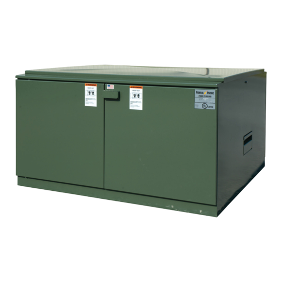
TYPE PSE PAD-MOUNTED SWITCHGEAR
These instructions are provided as a quick reference and are not intended as a substitute for the detailed instructions contained in Instruc-
tion Bulletin IB-2A-210. These instructions are intended to be performed by thoroughly trained, qualified personnel that are familiar with
the equipment, the operation and maintenance of the equipment and the hazards involved in performing the functions described in this
document and Instruction Bulletin IB-2A-210.
Before energizing the switchgear, remove all yellow and red shipping caps on bushings and bushing wells, and replace them with a suitable
system of insulated separable connectors (elbows), insulating protective covers, or plugs, as appropriate.
Failure to remove the shipping caps may result in flashover, equipment damage, serious personal injury, or death.
Load-break inserts and loadbreak elbows used in combination with the Federal Pacific Dead-
Front PSE Pad-Mounted Switchgear are rated for load switching of currents to 200 amperes
continuous. Consequently, the 200-amp elbow may be pulled, in accordance with the elbow
manufacturer's instructions, to perform the load-switching function. Pulling the energized elbow
interrupts the load current connected to the associated circuit. The elbow is then parked on
a standoff bushing. Then, only after the elbow has been parked, the fuse panel can be rotated
(pivoted) to expose the fuse that is to be removed. With the elbow removed, rotation of the fuse
panel does not involve any load switching. The removal of the fuse from the fuse panel can be
accomplished using the shotgun stick or, since the fuse once exposed is completely and visibly
isolated from voltage at both ends, and if standard operating practices permit, the fuse can be
removed by hand when wearing gloves insulated for the voltage involved.
1. Install and secure a feed-thru stand-off bushing on the parking stand. The feed-thru device
must be oriented so that it will not interfere with the operation of the hinged fuse-panel.
2. If switching of energized elbows is permitted, proceed to Step 3 below. If switching of energized
elbows is NOT permitted, test the circuit in accordance with the user's standard operating
practices and using equipment rated for the voltage involved to verify that the circuit is de-
energized.
3. After verifying the applicable de-energized/energized condition of the elbow to be
switched and following the elbow manufacturer's operating instructions:
a. Pull the elbow off the loadbreak insert and properly re-position it onto the feed-thru
stand-off bushing. Make certain that the connected high-voltage cable is retained within
the cable guide and moves so it is clear of the fuse panel, which must be free to pivot 90°.
b. Using equipment rated for the voltage involved, test the re-positioned elbow for voltage
through the uncovered loadbreak insert of the feed-thru.
c. After verifying that voltage is not present, properly install the grounding elbow in accordance
with the grounding-elbow manufacturer's instructions and the user's standard operating
practices, first clamping the ground connector to the ground buss and then installing the
grounding elbow on the unoccupied loadbreak insert of the feed-thru.
d. Ensure that the cables, feed-thru devices, and elbows are not located where they would
interfere with the operation of the fuse panel. Reposition as needed.
4. With the hook of the shot-gun clamp stick secured to the interlock latch grip rod on the fuse-
panel (see Figure 1), raise the latch to the horizontal position and verify that the interlock latch
locking rod is free of the notched latch brackets at the sides. See Figure 2.
1075 Old Airport Road • Bristol, VA 24201 Phone (276) 669-4084 • FAX (276) 645-8206 • www.federalpacific.com • ISO9001:2015
INSTRUCTIONS FOR OPERATION
DEAD-FRONT FUSE PANEL
15kV • 25kV
WARNING
DANGER
NOTICE
© 2021 Electro-Mechanical, LLC
INSTRUCTIONS FOR OPERATION DEAD-FRONT FUSE PANEL
TYPE PSE PAD-MOUNTED SWITCHGEAR
Figure 1. Interlock lever being raised
to unlocked position (or lowered to
locked position).
Figure 2. Fuse mounting being lowered
to access fuse (or raised to reinstall
fuse).
SECTION IB-2A-220
SEPT 2022
PAGE 1
Advertisement
Table of Contents

Related Manuals for FEDERAL PACIFIC PSE 15 kV


Summary of Contents for FEDERAL PACIFIC PSE 15 kV
- Page 1 Failure to remove the shipping caps may result in flashover, equipment damage, serious personal injury, or death. NOTICE Load-break inserts and loadbreak elbows used in combination with the Federal Pacific Dead- Front PSE Pad-Mounted Switchgear are rated for load switching of currents to 200 amperes continuous.
- Page 2 Every effort is made to ensure that customers receive an up-to-date instruction manual on the use of Federal Pacific products; however, from time to time, modifications to our products may without notice make the information contained herein subject to alteration.
Need help?
Do you have a question about the PSE 15 kV and is the answer not in the manual?
Questions and answers