Table of Contents
Advertisement
Quick Links
Advertisement
Table of Contents

Summary of Contents for Eltek Valere PSS30
- Page 1 Rectifier PSS30 USER MANUAL UM_PSS30_E_R00...
- Page 2 Info.industrial@eltekvalere.com Internet http://www.eltekvalere-industrial.com © Copyright ELTEK VALERE INDUSTRIAL 2008. All rights reserved. NOTE: Repetition, copying and /or taking possession of this user manual, even in extracts, with electronic or mechanical means, requires the written prior permission of the manufacturer. Eltek Valere Industrial ©2008...
- Page 3 The current revision status of this manual is the following: Revision: 00 Date: 2008-10-06 Revision Description of change Writer Date EVI layout and additional pictures inserted, minor text modi- fications (based on the original version 2008-10-06 “PSS30_E1_20071023.doc”) Eltek Valere Industrial ©2008 UM_PSS30_E_R00...
-
Page 4: Table Of Contents
10. Technical data........................2 10.1. General technical data.......................... 2 10.2. Specific data (depending on the type)....................2 10.3. Dimensional drawings, PSS30 (24, 48, 60 and 108V version)............. 2 10.4. Dimensional drawings, PSS30 (216V version)................. 2 Eltek Valere Industrial ©2008 UM_PSS30_E_R00... -
Page 5: Safety Instructions And Waste Disposal Rules
The above statement from EU directive 2002/96/EC applies to all electric modules installed within EU countries. In countries outside the EU, different rules may apply regarding waste disposal of electric modules. For more information about waste disposal of your discarded equipment, contact your ELTEK VALERE INDUSTRIAL partner. Eltek Valere Industrial ©2008 UM_PSS30_E_R00... -
Page 6: General
User manual Page 6 (28) 1. General The primary switched mode rectifier type PSS30 (named PSS in the following) delivers an output power to a maximum of 3.0kW. Typical applications are DC power supplies, uninterruptable power supplies with parallel connected batteries. -
Page 7: Available Options And Accessories
Connector set for input/output, PSS 216V 880-100-STK.03 Temperature sensor (LM335) integrated in a terminal end M5, 880-300-TMP.01 with 4m connection wire 19“ sub rack, 7U 880-MEC-BGT7.00 Photo: 19“ sub rack, 7U, for the integration of three rectifiers PSS Eltek Valere Industrial ©2008 UM_PSS30_E_R00... -
Page 8: Start Up Procedure
4. Operation All operation elements are fitted on the front panel of the module. The function of each individual operation element is described on the following pages. See also section 7. “Operation elements and connectors”. Eltek Valere Industrial ©2008 UM_PSS30_E_R00... -
Page 9: Functions
Primary Switch Mode Rectifier PSS30 User manual Page 9 (28) 5. Functions 5.1. Circuit diagram Picture: Schematic Block Diagram PSS30 Eltek Valere Industrial ©2008 UM_PSS30_E_R00... -
Page 10: Electrical Function Description
The output voltage for trickle charge is standard set. For the use of “Boost charge” or “Battery test”, the pins of the signal connectors are to be connected as described in section 7.3 “Electrical connectors”. Eltek Valere Industrial ©2008 UM_PSS30_E_R00... -
Page 11: Dynamic Regulation Of The Output Voltage
This signal is included in the collective failure signal of the rectifier. Additional there is an optocoupler signal (mains O.K.). For high input voltages (approx. >270V ) there is implied an automatic switch off function. Eltek Valere Industrial ©2008 UM_PSS30_E_R00... -
Page 12: Operation Monitoring
A collective failure is signalled with the LED “Bell symbol”. Furthermore overheating is signalled; criterion: Temperature of the heat sink > 90°C (the unit switches OFF). This signal is included in the collective failure signal. You have to reset the unit by ON/OFF switch. Eltek Valere Industrial ©2008 UM_PSS30_E_R00... -
Page 13: Signals
For PSS30, 24/48/60/110V version: The relay contacts between pin 14 and pin 15 of X2 are open and between pin 15 and pin 16 are closed at failure. For PSS30, 220V, only relay version: The relay contacts between are open a... -
Page 14: External Functions
The signalling voltage is 10-24V, the internal resistance is 2,7kOhm. The input is protected against reversed polarity. At higher supply voltages the current in the control circuit has to be limited to approx. 5-7mA with a series resistor (e. g. 6,8kOhm at 48/60V Eltek Valere Industrial ©2008 UM_PSS30_E_R00... -
Page 15: Discharge Test
. The voltage value can be adjusted by the user (see section 5.4). NOTE: For 60/108/216V units: For the connection to +V an additional series resistor is to be used (60 V: 18kOhm; 108 V: 56kOhm; 216V: 150kOhm). Eltek Valere Industrial ©2008 UM_PSS30_E_R00... -
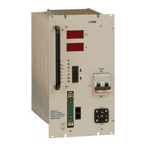
Page 16: Operation Elements And Connectors
LED indicators Adjustment keys „UP“ and „DOWN“ Input-side fuse; ON-/OFF switch Locking slide for the DC connector DC connector X2 (& signals) Two CAN-Bus connectors (RJ11, 6-pole) Mains connector X1 PE connector (M4 bolt) Eltek Valere Industrial ©2008 UM_PSS30_E_R00... -
Page 17: Front View/Operation Elements 216V Version
LED indications Adjustment keys „UP“ and „DOWN“ Input-side fuse; ON-/OFF switch DC connectors X2 Signals/CAN-Bus connectors X4 Mains connector X1 PE connector (M4 bolt) Eltek Valere Industrial ©2008 UM_PSS30_E_R00... -
Page 18: Electrical Connectors
Primary Switch Mode Rectifier PSS30 User manual Page 18 (28) 7.3 Electrical connectors AC-mains input (GDM-connector) for all PSS30 versions (connector X1) X1, pin Function L1 - Input N - Input DC output and signalling contacts (SUB-MIN-D-connector 21WA4), for 24, 48, 60 and 108V versions (connector X2):... - Page 19 216V version (connector X2): Function X2, pin (+) - output (+) - output (+) - voltage sense link control wire for active current sharing BUS ground (-) - voltage sense link (-) - output (-) - output Eltek Valere Industrial ©2008 UM_PSS30_E_R00...
- Page 20 Primary Switch Mode Rectifier PSS30 User manual Page 20 (28) Signals (connector X4 = 15 x COMBICON 1,5mm Pin assignment of X4 for PSS30/216V with signalling relay (without CAN-Bus) X4, pin Function (+) external switch on/off (-) external switch on/off optocoupler emitter optocoupler collector "Mains O.K."...
-
Page 21: Maintenance
Attention! Dust combined with moisture or water may influence or destroy the internal electronic cir- cuits. Dust inside the unit can be blown out with dry compressed air. The intervals between this checks depends on ambient conditions of the installed module. Eltek Valere Industrial ©2008 UM_PSS30_E_R00... -
Page 22: Trouble Shooting
V> (see section 5.4)! If the module still does not work even though all checks have been done, contact your sales agent or the ELTEK VALERE INDUSTRIAL service department. 9.2. Deviation of the output voltage - Operates the module in constant current mode (overload)? >Reduce the load! -
Page 23: Technical Data
≤ 3 % at load changes between 10 Dynamic voltage difference % - 90 % - 10 % of nominal output current (regulation time ≤ 1 ms) Short circuit capability continuous short circuit proof (constant current control) Eltek Valere Industrial ©2008 UM_PSS30_E_R00... - Page 24 “ signal via optocoupler const External ON/OFF if required Parallel operation max. 50 units, consumer load sharing approx.10% Design 1/3 x 19" unit for mounting in cabinets according to DIN 41494 Protection class IP 20 Cooling Fan cooling Eltek Valere Industrial ©2008 UM_PSS30_E_R00...
- Page 25 Input connection X1 angular plug type GDM 2011; 3- pole DC-output / signalling X2 24-108V : SUB-Min-D-connector 21WA4 216V Front side terminals 8x4mm COMBICON (DC-output); Front side terminals 15x1,5mm (signal contacts) Protective conductor connection bolt M4 Eltek Valere Industrial ©2008 UM_PSS30_E_R00...
-
Page 26: Specific Data (Depending On The Type)
48 to 60V 86,4 to 108V 173 to 216V 19,2 to 24V DC over voltage V> Threshold value 135V 270V Adjustment range 52 to 60V 66 to 75V 119 to 135V 238 to 270V 26 to 30V Eltek Valere Industrial ©2008 UM_PSS30_E_R00... -
Page 27: Dimensional Drawings, Pss30 (24, 48, 60 And 108V Version)
Primary Switch Mode Rectifier PSS30 User manual Page 27 (28) 10.3. Dimensional drawings, PSS30 (24, 48, 60 and 108V version) 10.4. Dimensional drawings, PSS30 (216V version) Eltek Valere Industrial ©2008 UM_PSS30_E_R00... - Page 28 Supplier: ELTEK VALERE INDUSTRIAL GmbH Schillerstraße 16 D-32052 Herford + 49 (0) 5221 1708-210 + 49 (0) 5221 1708-222 Email Info.industrial@eltekvalere.com Internet http://www.eltekvalere-industrial.com © Copyright ELTEK VALERE INDUSTRIAL 2008. All rights reserved.
Need help?
Do you have a question about the PSS30 and is the answer not in the manual?
Questions and answers