Advertisement
TECHNICAL DATA
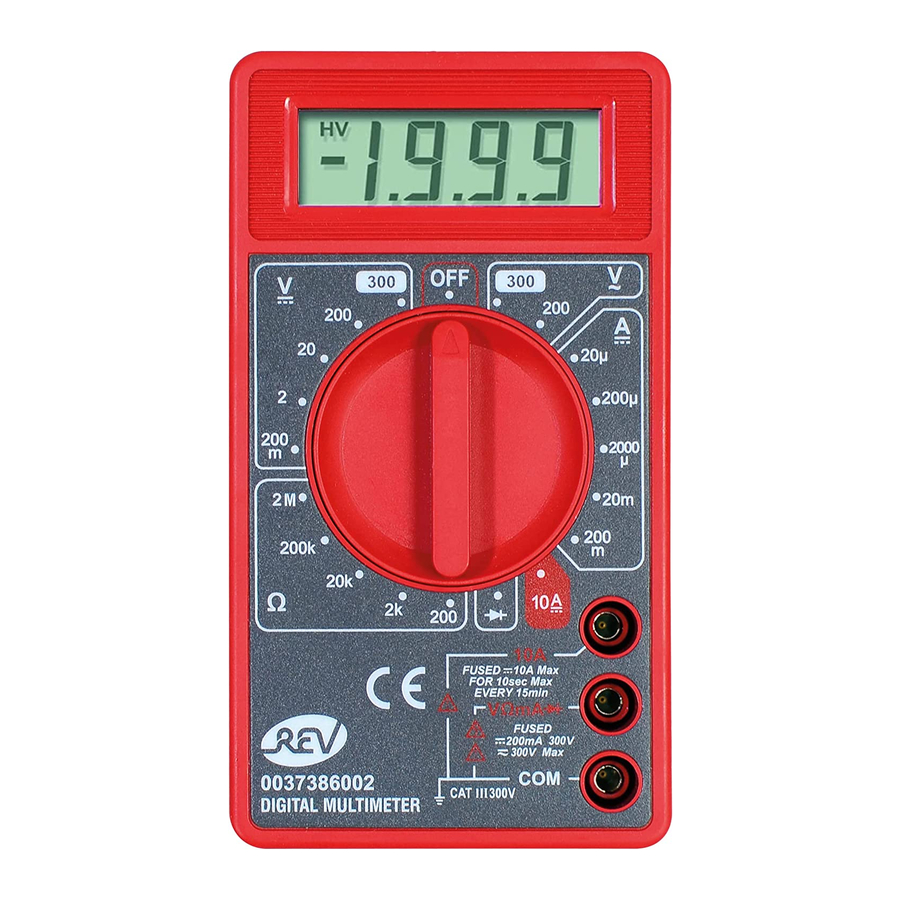
3½ - place LCD digital display with automatic polarity display
max. humidity:
storage <85%; operation: <75%
Operating temperature: 0° – +40°C
Storage temperature: -10° – +50°C
Battery: 6LR61 9 V-Block
Miniature fuse: F1= F250mAH, 300V
F2= F10AH, 300V
DESCRIPTION OF SYMBOLS

| Symbol | Description |
V  | Direct voltage (DC) |
V  | Alternating voltage (AC) |
| A | Direct current (DC) |
| Ω | Resistance (Ohm) |
 | Diode test |
 | Fuse |
 | Earth |
 | Shockproof (safety class 2) |
 | Caution, risk of danger |
 | Danger of electric shock |
SAFETY PRECAUTIONS
Use only by an electrician. This Digital Multitester complies with the overvoltage category CAT III. The proper condition of the device and the necessary adherence to the safety precautions in these operating instructions ae the basis for correct measurements.
The test tips and the Digital Multitester form a unit with regard to safety.
- Never use the tester if the device or the test cables are damaged or a malfunctions is suspected.
- Check the operation of the tester before each use by measuring a known voltage.
- Always disconnect the voltage-carrying test cable before the ground test cable.
- Do not touch the metal tips of the test tips during measurements.
- Voltage measurements to ground may only be conducted up to a maximum of 300Volts.
- Particular caution should be exercised during voltage measurements of:
> 60 volts direct current (DCV)
> 30 volts alternating current (ACV) - Measuring accessories for mains measure-ment, must meet measurement category III per IEC 61010-031.
CARE AND MAINTENANCE
- Before opening the device, the connection plugs of the test tips must be disconnected from the tester and from the wiring or circuits to be tested.
- A defective miniature fuse may only be replaced with one of the same type.
- After the housing is opened, the tester may not be used again until the housing cover is screwed to the back of the tester again.
- Always switch off the device after testing.
- Only use a damp cloth, possibly with mild detergent, to clean the surface. Do not use any abrasive or solvent-based cleaning materials.
CONDUCTING TESTS
Overrange Indication: „OL" is shown on the display. In case the "OL" is shown on the display stop the measurement and choose another measurement area.
Alternating current voltage measurement (ACV)
- Connect "red" test cable to the VΩ socket and the "black" test cable to the COM socket.
- Set the rotary switch to the necessary alternating current position (V∼).
- Connect the test cables with the circuit; measured values are shown on the LCD display
Direct current voltage measurement (DCV)
- Connect "red" test cable to the VΩ socket and the "black" test cable to the COM socket.
- Set the rotary switch to the necessary direct current position (V
![]() ). If the voltage to be measured is not known beforehand, set the rotary switch to the highest position and then reduce the value in stages until the most rational display is reached.
). If the voltage to be measured is not known beforehand, set the rotary switch to the highest position and then reduce the value in stages until the most rational display is reached. - Connect the test cables with the circuit; the measured values and polarity of the red test cable are shown on the LCD display (the polarity of the red test probe is positive "+").
 ). If the voltage to be measured is not known beforehand, set the rotary switch to the highest position and then reduce the value in stages until the most rational display is reached.
Direct current measurement (DCA)
For measurements between 1µA and 200mA
- Connect the "red" test cable to the mA socket and the "black" test cable to the COM socket.
- Set the rotary switch to the required direct current ampere position (A
![]() ).
). - Open the circuit where measurements are to be carried out and connect the test cables to the opening points.
- Measured cables are shown on the LCD display. The measurement range is fused with F250mAH
 ).
).For 200mA - 10A measurements
- Connect the "red" test cable to the 10A socket and the "black" test cable to the COM socket.
For measurements >2A: measuring time max. 10 sec., next measurement after 15 min. Measurements appear in the LCD. Measuring range fused with F10AH.

With small currents >10A the fuse may not trip yet and the measurement may appear. In this case abort the measurement immediately or the meter could be damaged.
Resistance measurement (OHM)

Only ever carry out resistance measurements in a currentless state.
- If the resistance that is to be measured is connected to an electrical circuit, switch the appliance off and discharge all capacitors before using the test probes.
- Connect "red" test cable to the VΩ socket and the "black" test cable to the COM socket.
- Set the rotary switch to the necessary ohm position (Ω).
- Connect the test probes with the resistance to be tested. Measured values are shown on the LCD display.
Diode test
- Connect "red" test cable to the VΩ socket and the "black" test cable to the COM socket.
- Set the rotary switch to the „
![]() " position.
" position. - Connect the red test probe to the anode and the black test probe to the cathode of the diode to be tested.
- The bias voltage load of the diode is shown in mV. "OL" is shown on the display in the event of incorrect polarity of the test probes.
 " position.
REPLACING BATTERY AND MINIATURE FUSE
Remove all test cables without fail before opening housing. The battery should be replaced as soon as  appears in the display. Undo the 3 screws on the rear of the digital multimeter. Remove the housing cover and insert a 9V battery – pay attention to correct polarity.
Miniature fuse
The miniature fuse only needs to be replaced very seldom, and when it does, it is almost always due to an operating error.
In this case you open the housing (as when replacing the battery) and replace the defective fuse with a new one of the same type (see Technical Data).
Observe safety precautions, maintenance and care instructions (see Technical Data)
DISPOSAL

In accordance with European defaults used electrical and electronics devices may no more be given to the unsorted waste. The symbol of the waste bin on wheels refers to the necessity of separate collection. Please help with environmental protection and see to it that this device is given to the for this purpose designated systems of waste sorting if you do not use it any longer.
DIRECTIVE 2012/19/EU of the EUROPEAN PARLIAMENT AND OF the COUNCIL of 4 July 2012 on waste electrical and electronic equipment (WEEE).
BATTERY

Batteries and accumulators are not to be disposed of in the normal house waste bin.
MEASURING TOLERANCES (AMBIENT TEMPERATURE 23°)
| Measuring range | Resolution | Measuring accuracy |
| Alternating voltage | ||
| 200V | 0.1V | ± 1,2% + 10 |
| 300V | 1V | |
| Direct voltage | ||
| 200mV | 0.1mV | ± 0,5% + 5 |
| 2V | 0.001V | ± 0,8% + 5 |
| 20V | 0,01V | |
| 200V | 0,1V | |
| 300V | 1V | ± 1,0% + 5 |
| Direct current | ||
| 20µA | 0.01uA | + - 1,2% + 5 |
| 200µA | 0.1uA | + - 1,0% + 5 |
| 2000µA | 1µA | |
| 20mA | 0.01mA | |
| 200mA | 0.1mA | + - 1,2% +5 |
| 10A | 0.01A | + - 2,0% +5 |
| Resistance | ||
| 200Ω | 0.1Ω | ± 1,2% + 5 |
| 2kΩ | 0.001KΩ | + - 1,2% + 5 |
| 20kΩ | 0.01KΩ | |
| 200kΩ | 0.1KΩ | |
| 2MΩ | 0.001MΩ | ± 1,2% + 5 |
Documents / ResourcesDownload manual
Here you can download full pdf version of manual, it may contain additional safety instructions, warranty information, FCC rules, etc.
Download REV Ritter EM830B - Digital Multitester Operating Instructions
Advertisement

Need help?
Do you have a question about the EM830B and is the answer not in the manual?
Questions and answers