
Summary of Contents for SCULPFUN S9 Z Axis Adjuster
- Page 1 KING GUBBY DESIGNS KING GUBBY DESIGNS KING GUBBY DESIGNS Sculpfun S9 Z Axis Adjuster INSTALLATION MANUAL INSTALLATION MANUAL INSTALLATION MANUAL...
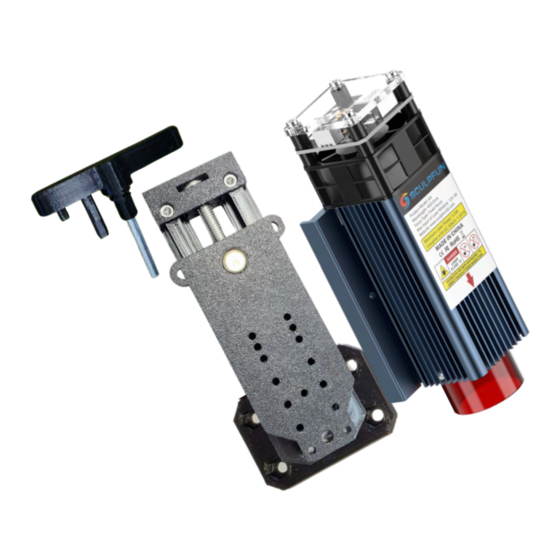
- Page 2 Included Parts For Z Axis Carriage Plate Module Plate S9 Adapter Plate M6 Bolt Barrel Nut Bolt Clip 4mm T Handle Wrench 6 x M3 Screws 6 x M4 Screws 4 x M4 Hex Nuts 6 x M3 Hex Nuts 2 x M4 Countersunk Screws...
- Page 3 This product is for the Sculpfun S9 This will not work for the Sculpfun S10...
- Page 4 IMPORTANT You need to check your home stop before turning on your laser, after installing the Z Axis. This is to avoid damage to your laser. With Z Axis Adjuster installed, home laser by hand Observe the space between your front rail and your module If the module comes in contact with the front rail, without hitting the home stop contact switch, you will need to move the contact switch to a position that renders it effective...
- Page 5 1st step: Prepping the Module Adapter Insert the M3 nuts into the available hexagons on the King Gubby Module Adapter. Then, remove the Sculpfun module from the Slider Plate by unscrewing the 2 thumb screws (Circled in yellow).
- Page 6 2nd Attach the Module Adapter Now, with the nuts installed and the Sculpfun module removed, face the King Gubby Module Adapter Plate's 'S9' to the Sculpfun Module, aligning the countersunk holes with the available holes in the module. Use the provided countersunk M4 screws to attach the Module Adapter Plate to the Sculpfun Module.
- Page 7 Module Plate (circled in red). Mount the Module Plate to the Module Adapter (Which should now be fastened to your Sculpfun Module) using four supplied M3 screws. Remember the M3 nuts that we 'sandwiched'? You are screwing these M3...
- Page 8 4th: Prepping the Carriage Plate Insert the M4 nuts into the available hexagons on the carriage plate.
- Page 9 5th: Attaching the Carriage Plate Attach the Carriage Plate to the laser carriage by using the four stock carriage 'thumb' screws. Slide them through the Sculpfun Carriage Slider Plate slots and tighten through the King Gubby Carriage plate at the 4 x M4 nuts.
- Page 10 6th: Assembling the Z Axis Now, slide the module plate (with module attached) onto the carriage plate (attached to carriage) via the dovetail channels. Insert the barrel nut in the provided open hole on the module plate (circled in red below). Next, slide the M6 bolt (75mm) through the hole in the top of the carriage plate, and screw to desired height, through the barrel nut.
- Page 11 Last step: Locking the Bolt Down Make sure the bolt head is touching the carriage plate and slide the bolt clip over the top of the bolt head to keep bolt from unscrewing while adjusting the axis. Set the remaining hex nuts in the fitted slots on the carriage plate and use the remaining M3 screws to attach the bolt clip to the carriage plate.
- Page 12 If you also got one of our Knob Upgrades, please click the image below or follow the link to see the manual. https://cutt.ly/zknobs...
- Page 13 Oh and... By the way, the reason the t-handle looks so funny is because it rests on your laser's aluminum extrusion. Keeps it out of reach of those tool trolls. Tag us in your projects Contact Us: KingGubbyDesigns@gmail.com...
- Page 14 IMPORTANT You need to check your home stop before turning on your laser, after installing the Z Axis. This is to avoid damage to your laser. With Z Axis Adjuster installed, home laser by hand Observe the space between your front rail and your module If the module comes in contact with the front rail, without hitting the home stop contact switch, you will need to move the contact switch to a position that renders it effective...
Need help?
Do you have a question about the S9 Z Axis Adjuster and is the answer not in the manual?
Questions and answers