Table of Contents
Advertisement
Quick Links
Advertisement
Table of Contents

Summary of Contents for Magnaflow xFrame
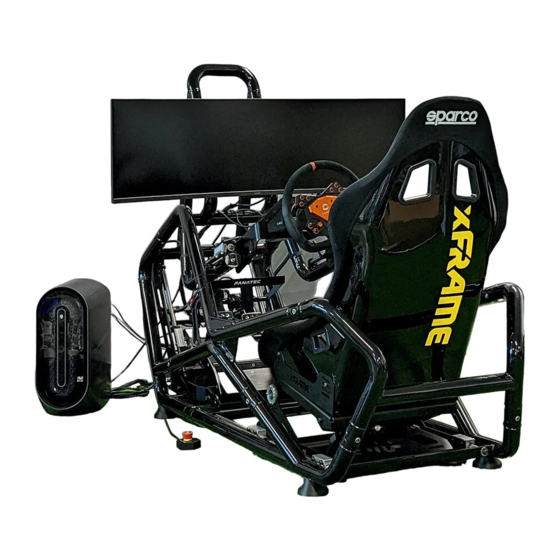
- Page 1 Owners Manual Magnaflow xFrame Racing Simulator Cockpit www.magnaflow.com...
-
Page 2: Introduction
We are proud you have chosen xFrame as the foundation of your new sim rig, now it’s time to start turning those wrenches and setting down some blistering lap times. -
Page 3: Table Of Contents
Table of Contents Welcome to xFrame 1. Introduction 2. Table of Contents 3. Product Safety 4. xFrame Overview Assembly Instructions 1. xFrame Chassis 2. Seat Sub-Assembly 3. Pedal Sub-Assembly 4. Steering Sub-Assembly 5. Electrical System 6. Shifter Mount [accessory] 7. Integrated Monitor Mount [accessory] 8. -
Page 4: Product Safety
As with all video games and simulators, always remain alert while using xFrame and avoid excessive play. Just like a real car or truck, do not operate xFrame if you are under the influence of drugs or alcohol. If your hands, wrists, arms, legs, feet or eyes become tired or sore while playing, or if you feel symptoms such as tingling, numbness, burning or stiffness, stop playing immediately and rest for several hours before playing again. - Page 5 200lbs when assembled. Do not attempt to transport xFrame with fewer than two people. Do not attempt to transport xFrame if you are injured or have limited strength or mobility. Do not lift xFrame overhead or in any manner which could risk dropping xFrame or injuring yourself. Do not transport xFrame vertically, upside down, with moving straps, or in any other way that could risk dangerous weight imbalance and sudden falling or dropping of xFrame.
-
Page 6: Xframe Overview
Overview Below is a general overview of xFrame and the chassis elements you need to know before you get started on the assembly process. Electrical Control Box Master On/Off Switch Selector Safety Key [shown with MagnaFlow flight tag] Selector Switch... -
Page 7: Assembly Instructions
Assembly Instructions Section 1: xFrame Chassis Required Tools: • Allen keys: 8mm Hardware Bag[s]: • Chassis hardware bag • Chassis Hardware ID Sheet NOTE: When assembling each of the welded tubular sub-assemblies, leave the connector bolts hand-tight until all sub-sections (A-F) are joined together. - Page 8 6. Install component F [Steering tubular sub-assembly] 7. Tighten all connector nuts & bolts until bottomed out and frame connectors in solid contact, then turn an additional quarter-turn of rotation to reach appropriate torque. Section Section 1: xFrame Chassis www.magnaflow.com...
- Page 9 Assembly Instuctions Section 2.1: Dynamic Formula/GT Seat Required Tools: • Allen keys: 4mm, 5mm, 6mm • Box wrench: 10mm, 11mm, 13mm Hardware Bag[s]: • Seat hardware bag • Seat Hardware ID Sheet Section 2: Seat Sub-Assembly www.magnaflow.com www.magnaflow.com...
- Page 10 1. Set component A [seat base upright] securely on a flat surface. 2. Install component B [lower arm] into component A, with the two rear slider blocks [components C] in as shown in Figure 2.2. Section 2: Seat Sub-Assembly www.magnaflow.com...
- Page 11 Assembly Instuctions 3. Install component D [upper arm] into component B in as shown in Figure 2.3. Section 2: Seat Sub-Assembly www.magnaflow.com...
- Page 12 Assembly Instuctions 4. Join component E [seat base] to component D in the way shown in Figure 2.4. Ensure that the nylon washers [component W4] are placed properly between each metal junction. Section 2: Seat Sub-Assembly www.magnaflow.com...
- Page 13 NOTE: It can be helpful to apply a small amount of petroleum lubricant to the edges of the tube on the Seat Base Assembly where you will be inserting components F in order to prevent potential noise or friction when assembled. Section 2: Seat Sub-Assembly www.magnaflow.com...
- Page 14 Assembly Instuctions 6. Install component G [sheet metal hanger] on component A [seat base upright] with the indicated hardware Figure 2.6. Section 2: Seat Sub-Assembly www.magnaflow.com...
- Page 15 Figure 2.7. Make sure to use the extended linear actuator in this step. Using the retracted actuator will cause difficulty in accessing and assembling this assembly moving forward. Section 2: Seat Sub-Assembly www.magnaflow.com...
- Page 16 8. Join the shaft of the linear actuator [component H] to the arm assembly in the manner shown in Figure 2.8. Ensure that the nylon washers [component W4] are placed properly between each metal junction. Section 2: Seat Sub-Assembly www.magnaflow.com...
- Page 17 Assembly Instuctions 9. Install the seat assembly brace [component I] in the location indicated in Figure 2.9. Section 2: Seat Sub-Assembly www.magnaflow.com...
- Page 18 Assembly Instuctions Section 2.2A: Seat Linear Rail System Section 2: Seat Sub-Assembly www.magnaflow.com...
- Page 19 [component C] as shown in Figure 2.11. NOTE: It can be helpful to apply a small dab of petroleum jelly to the back side of the linear rail locking shoe to help hold it in place during installation. Section 2: Seat Sub-Assembly www.magnaflow.com...
- Page 20 Figure 2.12. Leave the eight [8] M8 mounting bolts hand-tight. 3. Install both rear linear sliders onto the seat base assembly as indicated in Figure 2.12. Leave the six [6] M8 mounting bolts hand-tight. Section 2: Seat Sub-Assembly www.magnaflow.com...
- Page 21 4. To align all four [4] of the linear sliders, insert both linear shafts [components J] fully through the linear sliders as shown in Figure 2.13. Fully tighten all eight [8] M8 bolts securing the front linear sliders in place. Leave the rear linear sliders loose for now. Section 2: Seat Sub-Assembly www.magnaflow.com...
- Page 22 Assembly Instuctions 5. Remove both linear rails from the seat base assembly, and install the linear rail retaining hardware [Hardware ID: B4 & W5] on one side of both rails as indicated in Figure 2.14 Section 2: Seat Sub-Assembly www.magnaflow.com...
- Page 23 6. Lift and insert the completed F-GT seat assembly into position as shown in Figure 2.15. Then, lift the chassis [one side or end at a time] and place the chassis support feed un- derneath in the locations specified in Figure 2.15. Section 2: Seat Sub-Assembly www.magnaflow.com...
- Page 24 Install front rail hardware [Hardware ID: B4 & W5] to secure the seat assembly in position as shown in Figure 2.16. 8. Tighten the front rail retaining hardware till they bottom, then a half turn more. Section 2: Seat Sub-Assembly www.magnaflow.com...
- Page 25 Section 2.3: Seat Linear Rail Tensioning and Slider Alignment 10. If you are using the xFrame Seat Brackets and Sparco Seat, complete Section 2.4 before continuing. If you are using a seat and bracket combination of your own, install them now.
- Page 26 Assembly Instuctions Section 2.4: Bucket Seat Installation Section 2: Seat Sub-Assembly www.magnaflow.com...
- Page 27 Sparco bucket seat is in position and securely fastened to both universal seat brackets. 3. Fully tighten the four [4] M8 bolts from Step 2. 4. With the bucket seat fully installed, you may apply the provided xFrame decal if you wish to do so. Section 2: Seat Sub-Assembly...
-
Page 28: Pedal Sub-Assembly
Assembly Instructions Section 3.1: Pedal Base Plate Assembly Required Tools: • Allen keys: 4mm, 5mm, 6mm • Box wrench: 10mm, 13mm, 17mm Hardware Bag[s]: • Pedal hardware bag • Pedal hardware ID Sheet Section 3: Pedal Sub-Assembly www.magnaflow.com www.magnaflow.com... - Page 29 Assembly Instructions 1. Locate component A [pedal base plate] and install components B [left and right pillow block bearings] as shown in Figure 3.2. Use four [4] B10 bolts to secure. Section 3: Pedal Sub-Assembly www.magnaflow.com...
- Page 30 Assembly Instructions 2. Join components C [left and right linear sliders] to component B as shown in Figure 3.3. Be sure to have the small, unthreaded spacer in place [component D] when assembling. Section 3: Pedal Sub-Assembly www.magnaflow.com...
- Page 31 Assembly Instructions 3. Install the left and right cross brace adapters [components E] to the left and right linear sliders [components C] as shown in Figure 3.4. Leave this hardware hand-tight. Section 3: Pedal Sub-Assembly www.magnaflow.com...
- Page 32 Assembly Instructions 4. Install the linear slider cross-brace [component F] in orientation shown in Figure 3.5. As with the previous step, leave these bolts hand-tight for now as well. Section 3: Pedal Sub-Assembly www.magnaflow.com...
- Page 33 Assembly Instructions Section 3.2: Pedal Rail Upright Installation 1. Install the left and right pedal uprights [components G and H respectively] into the pedal tubular sub-assembly [chassis component B] as shown in Figure 3.6. Section 3: Pedal Sub-Assembly www.magnaflow.com...
- Page 34 3.7. NOTE: Component I often comes with small set screws in the central bearing hole. If yours has these, remove and dispose of them as they can cause issues with hardware clearance later on. Section 3: Pedal Sub-Assembly www.magnaflow.com...
- Page 35 Assembly Instructions 3. Install the blue nylon bushing [Hardware ID: NB1] into both left and right pedal angle arms in the orientation shown in Figure 3.8. Section 3: Pedal Sub-Assembly www.magnaflow.com...
- Page 36 Assembly Instructions 4. Install both left and right Pedal Angle Arms [components J and K respectively] into position as indicated in Figure 3.9. Section 3: Pedal Sub-Assembly www.magnaflow.com...
- Page 37 5. Install the Articulating Linear Actuator Brace [component M] and the Fixed Brace [component N] in the orientation shown in Figure 3.10. NOTE: Make sure the lower brace is centered between both pedal angle arms prior to tightening the hardware. Section 3: Pedal Sub-Assembly www.magnaflow.com...
- Page 38 Section 3.2 in the orientation shown in Figure 3.12. Be sure to apply 2-3 drops of Loctite thread locker to the bolt threads prior to installation [Hardware ID: B13]. This will help prevent unintended loosening through prolonged use. Section 3: Pedal Sub-Assembly www.magnaflow.com...
- Page 39 2. Install and fully tighten the retaining hardware on the pedal linear rails [components O] as shown in Figure 3.13. NOTE: Install the hardware onto the end of the rods with the machined hole (as shown above). Section 3: Pedal Sub-Assembly www.magnaflow.com...
- Page 40 NOTE: Over-tightening of the lower rail hardware may result in damage to the pedal rail upright. 5. Fully tighten the eight [8] M8 bolts from steps 3 and 4 of section 3.1. Section 3: Pedal Sub-Assembly www.magnaflow.com...
- Page 41 Assembly Instructions 6. Locate and install the two [2] unthreaded sleeves [component I] into the retracted linear actuator [component J] as in figure 3.15. Section 3: Pedal Sub-Assembly www.magnaflow.com...
- Page 42 Assembly Instructions 7. Install the linear actuator with the supplied hardware in the orientation shown in Figure 3.16. Ensure the washers [Hardware ID: W1] are placed correctly between the actuator and brace. Section 3: Pedal Sub-Assembly www.magnaflow.com...
- Page 43 9. Finally, Install the two Locking Shaft Collars onto the rail, and above both linear sliders [component C], one Locking Shaft Collar per side. WARNING: Leave the Locking Shaft Collars loose for now. See xFrame Tuning section for instructions on proper setup and usage. Section 3: Pedal Sub-Assembly www.magnaflow.com...
-
Page 44: Steering Sub-Assembly
Assembly Instructions Section 4 Steering Assembly Required Tools: • Allen keys: 5mm, 6mm • Box wrench: 13mm • Hardware Bag[s]: • Steering hardware bag Section 4: Steering Sub-Assembly www.magnaflow.com www.magnaflow.com... - Page 45 Figure 4.2. Apply 2-3 drops of Loctite thread locker to each bolt’s threads. 2. Fully tighten the eight [8] M8 bolts from Step 1. If you are using the xFrame Front Steering Mount, skip to Section 8 before continuing. If you are using the included Bottom Mount, continue to step 3.
- Page 46 3. The following steps reference the bottom-mount wheelbase plate but are the same for the front-mount. 4. With the wheelbase plate of your choice [component D, bottom mount shown] install the two [2] nylon bushings [Hardware ID: NB2] in the orientation shown in Figure 4.3 Section 4: Steering Sub-Assembly www.magnaflow.com...
- Page 47 Figure 4.4 using 2-3 drops of Loctite thread locker on only the bolt threads [Hardware ID: B3]. Install the adjustable locking handles, but DO NOT apply Loctite thread locker to their threads. Section 4: Steering Sub-Assembly www.magnaflow.com...
- Page 48 Figure 4.5 NOTE: It will be helpful to apply a small amount of rail lubricant to the locking shoes to help hold them in place while inserting the linear rails. Section 4: Steering Sub-Assembly www.magnaflow.com...
- Page 49 7. Locate the steering linear rails [component G] and install the locking hardware on the appropriate end as shown in Figure 4.6. NOTE: Install the hardware onto the end of the rods with the machined hole (as shown above). Section 4: Steering Sub-Assembly www.magnaflow.com...
- Page 50 NOTE: It may be easier to rest the steering sub assembly on the steering weldment tubes and insert one rail at a time. Be sure to wrap the steering weldment tubes with a lint-free cloth to avoid scratching the powder coat in these areas. Section 4: Steering Sub-Assembly www.magnaflow.com...
- Page 51 Once operating smoothly, fully tighten the retaining bolts. 10. Install both locking knobs [components H] into the linear sliders as in figure 4.8. Section 4: Steering Sub-Assembly www.magnaflow.com...
-
Page 52: Electrical System
Assembly Instructions Section 5.1: Electrical Control Box Installation 1. Locate the xFrame electrical control box and securely fasten it to the Fixed Cross Brace of the pedal assembly in the orientation shown in Figure 5.1. NOTE: Locate the two nylon washers between the electrical control box and the Fixed Cross Brace. - Page 53 • Electrical Hardware ID Sheet 1. Locate one [1] of the 54” long double four-pin wire leads [component A] and connect one end to the linear actuator Toggle Switch [component B] in the manner shown in Figure 5.2. Section 5: Electrical System www.magnaflow.com...
- Page 54 NOTE: Apply a thin layer of assembly lube to the o-rings on the toggle switch and to the inner surface of the steering weldment tubes. Section 5: Electrical System www.magnaflow.com...
- Page 55 Assembly Instructions 4. Locate the second 54” long double four-pin wire lead [component A] and connect one end to the Linear Actuator Selector Switch [component C]. Section 5: Electrical System www.magnaflow.com...
- Page 56 2. NOTE: Apply a thin layer of assembly lube to the o-rings on the selector switch and to the inner surface of the steering weldment tubes. Section 5: Electrical System www.magnaflow.com...
- Page 57 8. With both switches installed in their respective locations, it is time to connect both switches to the electrical control box from Section 1. Please refer to Figures 5.8, 5.9, 5.10 and 5.11 for proper cable routing and soft-tie locations. Section 5: Electrical System www.magnaflow.com...
- Page 58 Assembly Instructions Section 5: Electrical System www.magnaflow.com...
- Page 59 PWR plug on the electrical control box. Then plug the power supply itself in to a non-GFCI wall socket, or a surge protector/power strip. NOTE: Make sure any excess cable is appropriately managed, and out of the way of any articulating or moving components. Section 5: Electrical System www.magnaflow.com...
-
Page 60: Shifter Mount [Accessory]
Assembly Instructions Section 6.1: Shifter Mount Installation Required Tools: • Allen keys: 5mm, 6mm Hardware Bag(s): • Shifter hardware bag Section 6: Shifter Mount www.magnaflow.com www.magnaflow.com... - Page 61 1. Install the Shifter Interface Plate [component A] to the desired accessory mount location [Left or Right] as shown in Figure 6.2. NOTE: Do not over-tighten the two shifter interface bolts. Doing so may cause damage to the threaded frame insert. Section 6: Shifter Mount www.magnaflow.com...
- Page 62 Assembly Instructions 2. Install the Shifter Base Plate [component B] in the orientation shown to the Shifter Interface Plate [component A] as indicated in Figure 6.3. Section 6: Shifter Mount www.magnaflow.com...
- Page 63 1. Locate the monitor mount tubular structure [component A] and place securely on a flat surface. Orient it such that the long, straight tubes are coincident to the surface and the bent ones are in the air. Section 7: Monitor Mount www.magnaflow.com www.magnaflow.com...
- Page 64 Assembly Instructions 2. Locate the VESA Clamp Back [components A] and VESA Clamp Front [component B] and secure them to the two from tubes as shown in Figure 7.2 Section 7: Monitor Mount www.magnaflow.com...
- Page 65 NOTE: Do not over-tighten the VESA clamping bolts. Doing so may strip your display hardware, and could result in serious injury or damage. Complete Step 4 only if your display’s bolt pattern is not on the VESA Mount Adapter. Section 7: Monitor Mount www.magnaflow.com...
- Page 66 Assembly Instructions 4. If the monitor you intend to use on your xFrame monitor mount has a bolt pattern that is larger than what is provided on the VESA Mount Adapter, use the supplied VESA Mount Extenders [component E], and install in the orientation shown in Figure 7.4 Section 7: Monitor Mount www.magnaflow.com...
- Page 67 Assembly Instructions 5. Install the completed monitor mount assembly onto the xFrame chassis in the orientation shown in Figure 7.5. Make sure the orient the four [4] aluminum profiled spacers [components G] such that the profiled side is fully contacting the chassis.
- Page 68 [componenets B & C] in the orientation shown in Figure 8.1 2. With both braces securely fastened, install the assembly into the steering weldment the same way as the bottom mount wheelbase plate. Refer back to Assembly Section 4. Section 8: Front Mount Plate www.magnaflow.com www.magnaflow.com...
-
Page 69: C: Xframe Tuning
Tuning • Pedal Tuning & Adjustments Prior to first use or after any installation of different pedals, the pedal stops must be set accordingly. The pedal stop collars are designed to set the height of your pedals for your desired Formula seating position. The pedal stop collar position can vary between different pedal control models or manufacturers. - Page 70 Tuning 2. Select desired pedal base plate angle adjustment holes and securely fasten. NOTE: The outer-most hole [shown at left above] will create a Pedal Base Plate angle that is MORE LEVEL. Conversely, the inner-most hole [shown at right above] will create a Pedal Base Plate angle that is MORE VERTICAL.
- Page 71 Tuning 3. Loosen both pedal stop collars without fully removing. Make sure the pedal stop collars freely slide along the pedal rail and rest them on the aluminum slider blocks. 4. Actuate the pedal assembly all the way up to the maximum pedal base plate height, while watching to avoid any collision with pedal controls and the frame.
- Page 72 Tuning 5. With the Pedal Base Plate at its highest location, sit inside the simulator [with the seat in formula position as well] and ensure the pedal face angle is satisfactory. If adjustment is required, simply repeat step 2 until the angle is correct.
- Page 73 User Assembly kit in the locations indicated in figure 3.11. NOTE: The stick-on rubber bumpers are used to help secure the entire pedal assembly at the lowest GT position by being compressed. xFrame will function without them, but you can experience small amounts of movement in the lowest GT position if used without them.
-
Page 74: Seat & Bracket Adjustments
Tuning • Seat Tuning & Adjustments While the electronic seat actuation mechanism is designed to ideally operate with a user weighing less than 210lbs, it is rated to effectively lift a user up to 250lbs. Users weighing more than 210lbs may notice a reduction in actuation speed. If this is the case, you may opt to switch the linear actuator hanger to the alternate ,more rearward set of hardware holes [described previously in Seat-Sub Assembly instructions]. -
Page 75: Shifter Mount Adjustments
Tuning • Shifter Tuning & Adjustments The Shifter Base Plate can be installed in an inboard or outboard orientation, depending on the desired shifter location. An outboard configuration, as described in Section 6 of Assembly Instructions, will place the shifter base plate [and shifter] farther away [laterally] from the user. -
Page 76: Hardware Compatibility
Hardware Compatibility xFrame was designed to fit controls from leading simulation brands. A list of peripheral compatibility is below, with bolt patterns for all mounting points provided in following pages. If your hardware is not listed, compare measurements to determine compatibility. -
Page 77: Sim Racing Peripherals
• Bottom Mounted Steering Wheelbases xFrame comes out of the box with a bottom mount compatible wheelbase plate. Refer to the compatibility sheet on the first page of this section for known compatible parts, or cross-reference the below drawing to check fitment of other wheelbases. - Page 78 • Front Mounted Steering Wheelbases The xFrame Front Steering Mount is an accessory designed for those who want to utilize a wheelbase that is front-mount compatible. Our 4 slot design gives the freedom to accommodate many different wheelbase flange patterns. Refer to the compatibility sheet on the first page of this section for known compatible parts, or cross-reference the below drawing to check fitment of other wheelbases.
- Page 79 • Sim Racing Pedals xFrame was designed to accommodate most leading pedal sets as well as individual pedals on its pedal base plate. Refer to the compatibility sheet on the first page of this section for known compatible parts, or cross-reference the below drawing to check fitment of other pedals or pedal sets.
- Page 80 • Sim Racing Shifters & Handbrakes The xFrame Shifter Mount was designed to accommodate most leading sim racing shifters, as well as some handbrakes. Refer to the compatibility sheet on the first page of this section for known compatible parts, or cross-reference the below drawing to check fitment of other shifters or handbrakes.
-
Page 81: Racing Seats
• Racing Seats xFrame is designed to accommodate the majority of modern fixed-back racing seats, namely those that are side-mounted using mounting brackets [either our optional xFrame Seat Brackets or others made my seat or aftermarket manufacturers], but in certain cases bottom-mounted seats may be accommodated as well. -
Page 82: Operating Procedures
IMPORTANT! xFrame has been designed to support seated adjustments [e.g. performing electronic adjustments while a user is sitting in xFrame] for users from 60lbs [27kg] up to 250lbs [114kg]. If users in the upper end of this range desire faster actuating motion, they may use the alternative set of seat actuator mounting holes. - Page 83 Positioning Order of Operations Pedal Setup First set your pedals to GT or Formula position to help locate yourself in xFrame. Seat Angle Before adjusting seat depth, set your seat angle as reclining moves you farther from the pedals and will require sliding the seat farther forward the lower you recline.
-
Page 84: Actuators & Duty Cycle
Actuators & Duty Cycle Linear Actuators xFrame uses two high-force linear actuators to handle the task of adjusting your pedal height and seat inclination. These strong electronic devices are rated to handle the loads and conditions outlined in this manual. Should any issues ever arise with your linear actuators, stop usage and contact MagnaFlow immediately. - Page 85 Remove the safety key whenever you exit xFrame to prevent unintentional actuation. Keep the safety key stored out of reach of children and outside of xFrame when not in use. The key must be set to the neutral position [N] in order to be removed.
- Page 86 Should the overcurrent protection system repeatedly trip while operating xFrame within all specified guidelines, please contact customer support for assistance.
- Page 87 WARNING: As the Pedal Base Plate is actuated upwards, the Articulating Pedal Brace rotates downwards towards the ground, creating a potential pinch point. As a result, objects underneath the front of xFrame can be crushed or damaged, so keep all objects at least one foot away from the front area of the xFrame chassis.
- Page 88 BOTH of the two hand screws located at the lower front of the seat base. Then, grasping onto the tubular portion of xFrame for support if needed, slide your seat forward or backward until your legs rest at a comfortable distance from the pedals. Once in place, firmly lock BOTH of the two hand knobs to secure your position.
- Page 89 Once in place, firmly lock BOTH of the two screw handles to secure your steering wheel angle. WARNING: All of the manual adjustments on xFrame involve the sliding or moving of heavy metal components, and as such can cause pinching or crushing of objects or body parts.
-
Page 90: F: Cleaning & Maintenance
Make sure the AC adapter cord is fully inserted into the wall outlet or extension cord. Do not use xFrame if any damage has occurred to the AC power adapter. Do not power xFrame with any power supply unit besides the one originally provided with your xFrame. -
Page 91: Hardware Id Sheets
Hardware Identification Sheets NOTE: Hardware not to scale, please see ID sheets included with individual hardware bags. Pedal Hardware www.magnaflow.com... - Page 92 Hardware Identification Sheets NOTE: Hardware not to scale, please see ID sheets included with individual hardware bags. Seat Hardware www.magnaflow.com...
- Page 93 Hardware Identification Sheets NOTE: Hardware not to scale, please see ID sheets included with individual hardware bags. Steering Hardware www.magnaflow.com...
- Page 94 Hardware Identification Sheets NOTE: Hardware not to scale, please see ID sheets included with individual hardware bags. Chassis Hardware www.magnaflow.com...
-
Page 95: Frequently Asked Questions
This isn’t uncommon, but the usual fix is very simple. Loosen all 14 of the chassis bolts, enough for them to be easily movable, then re-tighten them starting from the bottom to the top. If the issue persists, retrying this with someone seated in xFrame can help. •... -
Page 96: Warranty & Contact Information
For warranty claims, or any other issues or information not outlined in this manual, call us at 1-800-990-0905 [Option 1 for MagnaFlow] or write us at www.magnaflow.com/pages/contact-us and we’ll get you back in the action.
Need help?
Do you have a question about the xFrame and is the answer not in the manual?
Questions and answers