Table of Contents
Advertisement
Quick Links
Advertisement
Table of Contents

Subscribe to Our Youtube Channel
Related Manuals for Mitsubishi Electric MXZ-2E52VAD


Summary of Contents for Mitsubishi Electric MXZ-2E52VAD
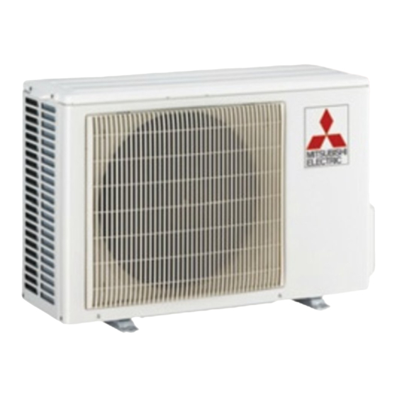
- Page 1 Split-type Air-Conditioner MXZ-2E52VAD MXZ-3E54VAD MXZ-4E71VAD For INSTALLER Installation Manual • This manual only describes the installation of outdoor unit. English When installing the indoor unit, refer to the installation manual of indoor unit.
- Page 2 Max. no. of bends Refrigerant Model Rated Fre- Breaker Max. height Power supply connecting per indoor unit / for per indoor unit / adjustment Voltage quency capacity difference *9 wire multi-system for multi system A *10 MXZ-2E52VAD 15 A 20 m / 40 m 20 / 40 4-core MXZ-3E54VAD 230 V 50 Hz 3-core 2.5 mm 25 m / 50 m 15 m 25 / 50 20 g/m 1.0/1.5 mm 25 A MXZ-4E71VAD 25 m / 60 m 25 / 60 Note: When connecting the MFZ-KJ series indoor unit(s) to this outdoor unit, charge additional refrigerant according to the instructions in the table below.
- Page 3 *4 Use a copper pipe or a copper-alloy seamless pipe. quired. (No additional charge is required for pipe length less than 40 m.) *5 Be careful not to crush or bend the pipe during pipe bending. Additional refrigerant = A × (pipe length (m) - 40) 1-3. SELECTING OPTIONAL DIFFERENT-DIAMETER JOINTS If the diameter of connection pipe does not match the port size of outdoor unit, use optional different-diameter joints according to the following table. (Unit: mm (inch)) Optional different-diameter joints Port size of outdoor unit (port size of outdoor unit → diameter of connection pipe) 6.35 (1/4) → 9.52 (3/8) : PAC-493PI MXZ-2E52VAD MXZ-3E54VAD MXZ-4E71VAD Liquid / Gas 9.52 (3/8) → 12.7 (1/2) : MAC-A454JP 9.52 (3/8) → 15.88 (5/8) : PAC-SG76RJ 12.7 (1/2) → 9.52 (3/8) : MAC-A455JP — — A UNIT 6.35 (1/4) / 12.7 (1/2) 12.7 (1/2) → 15.88 (5/8) : MAC-A456JP Refer to the installation manual of indoor unit for the diameter of connection...
- Page 4 Obstacles in front, behind and on side(s) Service space Provide space for service and maintenance as shown in the figure. • When installing the unit in an area that is enclosed with walls such as a verandah, be sure to have enough space as shown below. In this case, the air conditioning capacity and power consumption Service space might deteriorate. • When there is a lack of airflow or there is a possibility of becoming 100 or more short cycle, install an outlet guide and make sure there is enough space behind of the unit. 500 or more • When installing two or more units, do not install the units in front or behind each other. 100 or more 200 or more 350 or more 100 or more 350 or more 350 or more 500 or more 500 or more (Unit: mm) Height of the obstacle is 1200 or less 1-5. INSTALLATION DIAGRAM ACCESSORIES Check the following parts before installation. After the leak test, apply insulating (1) Drain socket material tightly so that there is...
- Page 5 2. OUTDOOR UNIT INSTALLATION 2-1. CONNECTING WIRES FOR OUTDOOR UNIT 1) Remove the service panel, top panel, front panel. Top panel 2) Loosen terminal screw, and connect indoor/outdoor unit connecting wire (B) from the indoor unit correctly on the terminal block. Be careful not to make mis-wiring. Fix the wire to the terminal block securely so that no part of its core is appeared, and no external force is conveyed to the connecting section of the terminal block. 3) Firmly tighten the terminal screws to prevent them from loosening. After tightening, pull the wires lightly to confirm that they do not move. 4) Perform 2) and 3) for each indoor unit. 5) Connect power supply cord (A). 6) Connect the demand control transmission cable to the terminal block for DRED Interface. 7) Fix indoor/outdoor unit connecting wire (B) and power supply cord (A) with the cable clamps. 8) Fix the demand control transmission cable with the cable strap. 9) Close the service panel , top panel, front panel securely. Make sure that 3-2. PIPE CONNECTION is completed. Service panel • After making connections between both power supply cord (A) and indoor/outdoor Front panel unit connecting wire (B), be sure to fix both cable and wire with cable clamps. Terminal block for power supply Terminal block Indoor/outdoor unit for DRED Interface <OUTDOOR UNIT> connecting wire (MXZ-2E) (MXZ-3E) (MXZ-4E) AS/NZS4755...
- Page 6 3-2. PIPE CONNECTION 1) Apply a thin coat of refrigeration oil (G) to the flared ends of the pipes and the pipe con- WARNING nections of the outdoor unit. Do not apply refrigeration oil on screw threads. Excessive When installing the unit, securely tightening torque will result in damage on the screw. connect the refrigerant pipes before 2) Align the center of the pipe with that of the pipe connections of the outdoor unit, then hand starting the compressor. tighten the flare nut 3 to 4 turns. 3) Tighten the flare nut with a torque wrench as specified in the table. • Over-tightening may cause damage to the flare nut, resulting in refrigerant leakage. • Be sure to wrap insulation around the piping. Direct contact with the bare piping may result in burns or frostbite. 3-3. INSULATION AND TAPING CAUTION 1) Cover piping joints with pipe cover. 2) For outdoor unit side, surely insulate every piping including valves. When there are the ports which are 3) Using piping tape (E), apply taping starting from the entry of outdoor unit.
- Page 7 4-4. LOCKING THE OPERATION MODE OF THE AIR CONDITIONER (COOL, DRY, HEAT) • Description of the function: With this function, once the operation mode is locked to either COOL/DRY mode or HEAT mode, the air conditioner operates in that mode only. * Changing the setting is required to activate this function. Please explain about this function to your customers and ask them whether they want to use it. [How to lock the operation mode] 1) Be sure to turn off the main power for the air conditioner before making the setting. 2) Set the “3” of SW1 on the outdoor controller board to ON to enable this function. 3) To lock the operation mode in COOL/DRY mode, set the “4” of SW1 on the SW871 outdoor controller board to OFF. To lock the operation in HEAT mode, set the same switch to ON.
- Page 8 HEAD OFFICE: TOKYO BUILDING, 2-7-3, MARUNOUCHI, CHIYODA-KU, TOKYO 100-8310, JAPAN BN79A289H01...
Need help?
Do you have a question about the MXZ-2E52VAD and is the answer not in the manual?
Questions and answers