
Summary of Contents for Canova SDSCV9000
- Page 1 Canova Operating Manual Product name: Canova embedding module Code: SDSCV9000 Manual revision: emission Edition date: November 2011...
- Page 2 Preface Canova embedding module is a modern workstation for embedding histological specimens in paraffin. This manual describes instrument operating, safety and maintenance information. The first section is “safety information” in which adopted symbols, warnings and precautions are described. The following section “specifications and installation” contains all information concerning installation instructions and features.
-
Page 3: Table Of Contents
Index PREFACE ..................- 1 - Destination of use ..............- 1 - SAFETY INFORMATION ..............- 3 - Mentioned agreement and graphic symbols ....... - 3 - Instructions of danger ..............- 3 - Instructions of warning ............... - 3 - Instructions of biocontamination .......... - Page 4 Antonio Canova worked for popes, kings, emperors and princes from all over the world, and was under the influence and charm of the seventeenth-century sculptor Gian Lorenzo Bernini, the undisputed master of the Baroque style.
-
Page 5: Preface
Preface 1.0 PREFACE 1.1 Destination of use Canova embedding module is a modern workstation for embedding histological specimens in paraffin. It is equipped with an electronic system for the constant working temperature control. IVD certified. Professional use of product. Designed and built for embedding histological specimens in paraffin blocks, Canova... - Page 6 Preface Legislative decree 27 January 2010 n.17, implementation of Directive 2006/42/EC on machinery and amending Directive 95/16/EC on lifts ISO9001:2008 Quality management systems - Requirements ISO13485:2003 Medical devices -- Quality management systems -- Requirements for regulatory purposes UNI CEI EN ISO14971:2009 Application of risk management to medical devices. UNI EN 591:2001 Instructions For Use For In Vitro Diagnostic Instruments For Professional UNI CEI EN 980:2009 Graphic symbols used for the medical devices labelling.
-
Page 7: Safety Information
Safety information 2.0 SAFETY INFORMATION 2.1 Mentioned agreement and graphic symbols Danger – The danger instructions signal situations that might cause death or serious lesions Caution – The caution instructions signal situations that might cause physical lesions or things damages. Biocontamination –... -
Page 8: Safety Training
Safety information 2.5 Safety training All the operators must be trained to use the instrument safely. After such training, the operators have understood that: • The instrument must be connected to a voltage source in accordance with electrical data label. •... -
Page 9: Storage And Handling
Storage and handling 3.0 STORAGE AND HANDLING For a correct maintenance and instrument working, it is necessary to observe all the instructions of this manual, and the environmental requisites below. Storage temperature range Working temperature range Storage humidity 80% The instrument can work with 80% relative humidity conditions for temperatures up to 31°... -
Page 10: Instrument Placement And Installation
Instrument placement and installation 4.0 INSTRUMENT PLACEMENT AND INSTALLATION 4.1.1 Unpacking Unpack instrument parts taking care to not damage them: each instrument part is checked before the shipping. Make sure about any serious damages to the packaging and to the instrument due to the transport. -
Page 11: Operating
Instrument placement and installation 4.1.3 Operating Move the instrument safely (at least two people) considering its weight of about 40 kg. Use lifting devices if necessary. Perform the following installation steps: • Place the instrument. Make sure it is installed on a plane surface. •... -
Page 12: Instrument Setting
Instrument setting 5.0 INSTRUMENT SETTING 5.1 Destination of use Canova embedding module has been designed and built for use in Anatomic Pathology laboratories for embedding histological specimens in paraffin blocks and for the following tasks: Melt solid paraffin and keep it liquid at pre-set temperatures Fill the embedding molds with liquid paraffin, taken from the dispenser Preserve the cassettes with specimens at the pre-set temperature. -
Page 13: Filling With Paraffin In Grain
Instrument setting 5.2.2 Filling with paraffin in grain Before switching on the instrument (even in Standby mode), it is necessary to load in the reservoir about 3.5 kg of paraffin in grains. It is a good practice to fill just below the reservoir rim near to the reference mark. -
Page 14: Instrument Parts
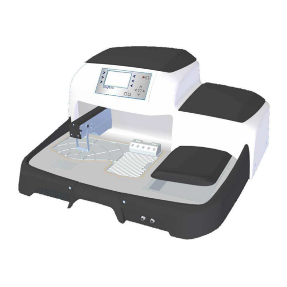
Instrument parts 6.0 INSTRUMENT PARTS 6.1 Paraffin reservoir The paraffin reservoir has a capacity of about 4 litres and is located at the top of the instrument. To fill the reservoir with solid paraffin, lift the lid and pour the grains up to the reference mark. -
Page 15: Paraffin Collecting Hot Plate
Instrument parts 6.3 Paraffin collecting hot plate The hot plate has been designed paying attention to dispose the exceeding paraffin in the grooves. The holes drain the refluent paraffin into the collection drawer positioned below the hot plate (Pic. 8). The hot plate cleaning can be done by using a brush or gauze, in order to carry the waste into the disposal pipes. -
Page 16: Cold Spot
Instrument parts 6.5 Cold spot For the rapid molds cooling has been studied a cold spot, to cool very quickly all kinds of molds on the market. Its big dimensions (70x60mm) allow to easily work with any kind of embedding. The temperature reached by the cold spot could change from -2 °... -
Page 17: Workspace Suction
Instrument parts 6.8 Workspace suction To ensure operator safety, the instrument is equipped with a suction tube below the dispenser, able to suction any harmful vapours on the workspace during routine operations. Pic. 12 6.9 Heated forceps & tamper connection At the bottom part of the instrument, next to the collection drawer, there are 2 connectors for the heated forceps and tamper. -
Page 18: Control Panel
Instrument parts 6.11 Control panel All instrument parameters can be set and managed by the keyboard, with 14 keys, on the control panel. The reached temperatures and all information are displayed on the colour 4.3' LCD. KEY NUMBERING Pic. 16 Pic. - Page 19 Instrument parts Press key 11, in the different menus, to move the cursor leftwards. Pres key 12 to confirm the values set in the different menus. Press key 13, in the different menus, to move the cursor rightwards. Press key 14 to increase the values or to move downwards the cursor in the different menus.
- Page 20 Instrument parts Press this key to clear the data just changed in the menu and return to the previous setting. Icon to access TEMPERATURES SETTING MENU; press the key to access TEMPERATURE adjustment. Icon to access MENU for setting of holder temperature. Icon to access MENU for setting of cold spot temperature.
-
Page 21: Operating Procedure
Operating procedure 7.0 OPERATING PROCEDURE Instrument STANDBY mode (energy saving) The embedding center turns on, pressing the electrical switch placed on the back of the instrument (Pic. 19). When the switch is on the ON position and the electrical circuits are powered, the instrument enters in STANDBY mode. - Page 22 Control panel functions 7.1 CONTROL PANEL FUNCTIONS SWITCHING ON SCREEN STANDBY SCREEN Pic. 19 Pic. 20 When the instrument is switched on, the display shows the screen as in Pic. 20. After switching on, when the loading ends, the display shows the standby mode screen (Pic. 21).
- Page 23 Control panel functions 7.2 HEATED FORCEPS MENU Pressing 5 Pic. 24 Pic. 25 Pic. 26 Pic. 27 From the main screen (Pic. 25), press the key 5 to access FORCEPS MENU (Pic. 26). In pos.2 and 5 (in blue), are shown the temperatures of the 2 forceps. When switching on, those numbers appear in blue (Pic.
-
Page 24: Control Panel Functions
Control panel functions Pic. 29 Pic. 30 In the bottom of the screen, it is possible to see the numbers that indicate the hours missing to the next expiry of each forceps. Shortly before the forceps expiry (from 100 hours), the number of remaining hours is red, while in the main screen, on the forceps symbol in pos.5, appears the warning symbol (Pic. -
Page 25: Setting Menu
Control panel functions 7.3 SETTING MENU Pressing 6 Fig. 32 Pic. 33 Pic. 34 From the main screen (Pic. 34), press the key 6 to access SETTING MENU (Pic. 35). From this menu: - press the key 1 to go to DATE AND TIME MENU - press the key 2 to go to TEMPERATURE SETTING MENU - press the key 3 to go to CALENDAR PLANNING MENU - press the key 4 to go to ALARM MENU... -
Page 26: Temperature Setting Menu
Control panel functions 7.5 TEMPERATURE SETTING MENU From the SETTING MENU (Pic. 39), press the key 2 to access TEMPERATURE SETTING MENU (Pic. 40). From here, press the key 2 to go to the heated point setting: press the key 5 to go to the cold spot setting. -
Page 27: Planning Calendar Menu
Control panel functions 7.6 PLANNING CALENDAR MENU From the SETTING MENU (Pic. 43), press the key 3 to access PLANNING CALENDAR MENU (Fig. 44) from which it is possible to set the days and hours of the heated points switching on/off. -
Page 28: Alarm Menu
Control panel functions 7.7 ALARM MENU From SETTING MENU (Pic. 45) press the key 4 and access ALARM MENU (Pic. 46). From here, in pos. 1, it is possible to see next filter expiry date. Pressing 4 Pic. 45 Pic. 46 Pressing 2 Press the key 2 from ALARM MENU (Pic. -
Page 29: Filter Expiry Alarm
Control panel functions 7.8 FILTER EXPIRY ALARM 30 days before filter expiry, in the main screen (Pic. 50) in pos.6, appears a warning symbol. It signals the next filter expiry. Pressing 6 Pic. 49 Pic. 50 Pressing 4 Press the key 6, from the main screen (Pic. 50), to access SETTING MENU (Pic. -
Page 30: Expired Filter Alarm
Control panel functions 7.9 EXPIRED FILTER ALARM On filter expiry, in the main screen (Pic. 54), flashes, in the display centre, the alarm symbol alternated to the filter symbol, with an acoustic alarm. The alarm symbol, in pos.4, flashes too. Pressing the key 4, appears the screen in Pic 55, where the code (supplied with new filters) has to be entered in order to enable the instrument functioning for other 6 months. -
Page 31: Overheating Alarm
Turning off procedure 7.10 OVERHEATING ALARM In case of overheating alarm of one or more instrument points, in the main screen flashes, at the centre and in pos.4, the alarm symbol (Pic. 57) with an acoustic signal. Pressing the key 4, appears the screen as in Pic 58 where it is highlighted the alarm type with a code identifying the instrument area. -
Page 32: Performances And Limitations
Performances and limitations 9.0 PERFORMANCES AND LIMITATIONS Canova embedding module is a modern workstation for embedding histological specimens in paraffin. Users might use the equipment according to the limits described in this manual and following moral and good-sense procedures. Diapath S.p.A. leaves out any contractual and external contractual responsibilities for damages caused by any mistakes done working in the inobservances of instructions given by the manufacturer. -
Page 33: Quality Control
Quality control 10.0 QUALITY CONTROL Diapath S.p.A. uses quality management system ISO 9001:2008 and ISO 13485:2003 to project, make and improve the technical scientific solution for the customer in medical and diagnostic in vitro systems, assuring high quality services with the help of an highly qualified and motivated staff to contribute towards the improvement of Diapath S.p.A. -
Page 34: Specifics And Installation
Specifics and installation 11.0 SPECIFICS AND INSTALLATION Embedding center - Canova Physical features: Instrument dimensions (WxDxH) 730x675x350 mm Weight 40 Kg Electrical features: Tension 230 V~ ±10% Frequency 50/60Hz Voltage 10 A Power 1000/2000W Power cord Schuko plug Fuses T10 AL 250V... -
Page 35: Cleaning And Maintenance
Cleaning and maintenance 12.0 CLEANING AND MAINTENANCE Important! Switch off the instrument before cleaning. Important! We suggest using suitable D.P.I. (gloves, masks, etc. according to the situations) to perform in safety these cleaning procedures. LCD display cleaning 12.1.1 To clean the display, use a standard clearing detergent for screen (use it in accordance with the instructions given by the detergent manufacturer). -
Page 36: Fuse Replacement
Fuse replacement 13.0 FUSE REPLACEMENT To replace the fuses: • Make sure that the power cord is disconnected and the switch is turned off in OFF position (Fig. 59). Fig. 59 • Open fuse box with a light pressure on the point shown in Fig. 60. Fig. -
Page 37: Scheduled Maintenance
Scheduled maintenance 14.0 SCHEDULED MAINTENANCE Important! We suggest using suitable D.P.I. (gloves, masks, etc. according to the situations) to perform in safety these cleaning procedures. 14.1 Filter expiry The instrument is equipped with a filter to reduce harmful vapours from the workspace. To ensure functioning efficiency and to safeguard the operator, this filtering battery has a scheduled expiry of 6 months. -
Page 38: Wee Directive
WEE directive 15.0 WEE DIRECTIVE In compliance with EU Directive 2002/96/EC or waste electrical and electronic equipment (WEEE), this electrical product must not be disposed of as unsorted municipal waste. Please dispose of this product by returning it to the point of sale or to your local collection point or recycling. -
Page 39: Troubleshooting
Troubleshooting 16.0 TROUBLESHOOTING Problem Possible cause Corrective action Make sure the power cord is The reservoir doesn’t The instrument is connected and the main switch heat. switched off. is in ON position (switched on). The paraffin doesn’t Selected temperature Make sure paraffin features are melt completely. - Page 40 Troubleshooting Problem Possible cause Corrective action Make sure the power cord is The instrument is connected and the main switch The hot plate is cold switched off or in is in ON position (switched STANDBY mode. on). Hot plate The falling paraffin Selected temperature Make sure paraffin features are doesn’t melt...
-
Page 41: Spare Part List
Troubleshooting Problem Possible cause Corrective action The instrument is on Switch on the instrument. STANDBY mode. Light brightness LED lights don’t Press the key + to increase the regulation is to the LED lights switch on. brightness. minimum. Contact Diapath S.p.A or the LED lights are faulty. -
Page 42: Manual Information
Manual information 18.0 MANUAL INFORMATION It is forbidden partly or in full to modify the present manual in absence of any explicit authorization. Information contained in this manual are subject to changes without prior notice. Diapath S.p.A. has done as much as possible to assure the accuracy of the present manual. -
Page 43: Definition Of Adopted Symbols
Definition of adopted symbols 19.0 DEFINITION OF ADOPTED SYMBOLS In Vitro Diagnostic Medical Device Manufacturer Built in date Danger Disposal This product fulfils the requirements of Directive 98/79/EC on in vitro diagnostic medical devices See operating manual Heated surface or area Electric shocks risk Heated forceps connection Paraffin foot switch connection... -
Page 44: Warranty
Warranty 20.0 Warranty - 40 - MU_EN_Operating_Manual_Canova_embedding module_Rev.I°emiss_031111... -
Page 45: General Information
General information 21.0 GENERAL INFORMATION Diapath S.p.A. Via Savoldini,71 24057 Martinengo (BG) Italy Ph. (+39)0363.986.411 Fax (+39)0363.948.000 www.diapath.com info@diapath.com - 41 - MU_EN_Operating_Manual_Canova_embedding module_Rev.I°emiss_031111...