Advertisement
Quick Links
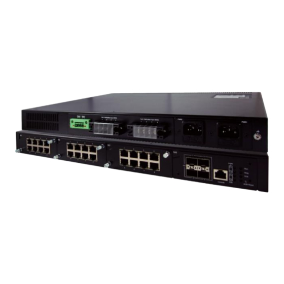
Industrial Managed Rack-Mount Modular
Gigabit Ethernet Switch
FLC-2528 GP/XP Series
Version 2.0
Updated in October, 2017
Inside the package you will find the following items:
■ Industrial Managed Rack-Mount Modular Gigabit Ethernet Switch x 1
■ Rack Mount Kit x 2
■ 4-pin Terminal block x 1 for the relay output
■ 3-pin Terminal block x 1~2 for the DC models power input
■ Protective caps for all SFP ports (Depend on purchased model)
■ Installation Guide x 1
Never install or work on electrical or cabling during periods of lightning activity.
Never connect or disconnect power when hazardous gases are present.
Warning:Hot Surface Do Not Touch.
Caution: CLASS 1 LASER PRODUCT. Do not stare into the laser!
This equipment should be installed indoor and not connect directly with equipment
installed outdoor.
I n d o o r
Throw the device must follow RoHS procedure to recycle
Front View
Dual AC / Dual DC /
SingleAC & Single DC model
1
2
3
4
1 2 3 4
M1
M2
M3
1
2
3
4
M4
1 2
PoE
PoE
1
5
2
6
10G
3
7
4
8
5
6
7
8
5 6 7 8
5
6
7
8
3 4 Console
PoE ALM Reset
Single AC model
M1
1
2
3
4
M2
1 2 3 4
M3
1
2
3
4
M4
1 2
PoE
PoE
1
5
2
6
10G
3
7
4
8
5 6 7 8
5 6 7 8
5
6
7
8
3 4 Console
PoE ALM Reset
Back View
AC redundant
for power up CPU board only
PWR2
Relay2
Relay1
PoE PWR2(Max Input 360W)
PoE PWR1(Max Input360W)
1
2
3
4
1
2
3
4
+
+
+ +
AC single
for power up CPU board only
Relay2
Relay1
PoE PWR2(Max Input360W)
PoE PWR1(Max Input360W)
1
2
3
4
1
2
3
4
+ +
_ _
+ +
_ _
DC redundant
for power up CPU board only
Relay2
Relay1
PoE PWR2(Max Input360W)
PoE PWR1(Max Input360W)
1
2
3
4
1
2
3
4
3 2 1
3 2 1
+ - F.G.
+ - F.G.
+ +
_ _
+ +
_ _
Mixing single redundant
(SingleAC & Single DC)
for power up CPU board only
DC1
Relay2
Relay1
PoE PWR2(Max Input360W)
PoE PWR1(Max Input360W)
3 2 1
1
2
3
4
1
2
3
4
+ - F.G.
+ +
_ _
+ +
_ _
1. Ground the device properly. You can use the FG pin in the terminal block. It is
required to connect to the grounds at all times to ensure overall maximum
performance.
2. If you opt to place the device on a rack, you will need to secure the rack
mounts kit on to the device before placing it on the rack. If you opt to place the
device on a surface, you can put on the foot rubbers to prevent the device from
sliding.
3. You can then choose whether to plug in the I/O ports at this point or do it later.
Next you can then proceed to connect the device to the LAN (switch or PC),
take care on using the RJ-45 connector; after this we can then proceed to the
device's settings.
4. The openings to the sides are for the devices heat dissipation. Please never
obstruct or cover them with any objects.
5. This switch's factory IP by default is 10.0.50.1 . you can access the device by
its Web UI once it is connected to a physical network (or using Management
Utility, for more information on Management Utility, please refer to its manual).
Please be aware that the PC needed for this procedure needs to be in the
same subnet, or you may refer yourself to the device User's Manual.
PWR
P1
Run
P2
Ring
P1
R.M.
P2
PWR
P1
Run
Ring
P1
R.M.
P2
PWR1
PWR1
PWR1
1
2
3
4
PoE PWR
_
_
+
+
1
2
3
+
+
-
3
2
1
DC PWR
_
+
F.G.
1
2
F.G.
-
Relay2
Relay1
Relay output
■ Power input : 110-220 VAC, 0.58 A Max, 64W Max (For AC version models)
48-57 VDC, 0.68A Max, 32.7W Max (For DC version models) 45-57 VDC,
8.4A Max, 370W Max (For 802.3af models)
51-57 VDC, 14.4A Max, 720W Max (For 802.3at models)
■ Alarm output : 1A@24A VDC for signal use only
4
-
3
+
Advertisement

Summary of Contents for Sbjlink FLC-2528 GP/XP Series
- Page 1 Never install or work on electrical or cabling during periods of lightning activity. sliding. Never connect or disconnect power when hazardous gases are present. FLC-2528 GP/XP Series Warning:Hot Surface Do Not Touch. 3. You can then choose whether to plug in the I/O ports at this point or do it later.
- Page 2 State Description remove it from its mounting. The initial installation should be done in a way that 1. Please contact your local dealers or Sbjlink Support at the PWR1/ Power is supplied from PWR1/PWR2 makes this as convenient as possible.
Need help?
Do you have a question about the FLC-2528 GP/XP Series and is the answer not in the manual?
Questions and answers