Table of Contents
Advertisement
Quick Links
Advertisement
Table of Contents

Related Manuals for Befaco BCMF3100

Summary of Contents for Befaco BCMF3100
- Page 1 BCMF3100 Coriolis Mass Flow Meter Operating Manual 1 / 35 www.befaproses.com...
-
Page 2: Table Of Contents
Content 1 BCMF Mass Flow Meter Overview ........................5 1.1 Main Features .............................. 5 1.2 Application ..............................5 1.3 Working Principle ............................6 2 Sensor Parameters ..............................7 2.1 Sensor Structure ............................7 2.2 Technical Parameters ..........................8 2.3 Sensor Dimension ............................9 3 Selection and Installation.............................12 3.1 Selection ..............................12 3.2 Installation ..............................13... - Page 3 4.9.1 Enter menu ............................21 4.9.2 Selection function ...........................22 4.10 BASICS menu structure .........................22 4.11 Factory setting menu structure ......................23 4.12 Display setting ............................25 4.12.1 DISP #1 setting ..........................25 4.12.2 DISP #2 setting ..........................26 4.12.3 DIGITS ............................26 4.12.4 CONSTRAST ..........................26 4.12.5 BK LIGHT ............................26 4.12.6 LANGUAGE ..........................26 4.13 Measurement setting ..........................26 4.13.1 DAMP TIME ..........................26...
- Page 4 4.17.2 Zero adjustment setting ......................31 4.17.3 Troubleshooting for ZERO CAL ....................31 4.18 COMM ...............................32 4.18.1 COMM selection ...........................32 4.18.2 RS485 ............................32 4.19 RECALL MEMO ............................32 4.20 Device status and output test ........................32 4.20.1 DEV.INFO ............................32 4.20.2 DEBUG ............................33 4.21 ADVANCED menu ...........................34 4.21.1 Flow K ............................34 4.21.2 CAL TEMP ............................34 4.21.3 M.FLOW MAX/MIN ........................34...
-
Page 5: Bcmf Mass Flow Meter Overview
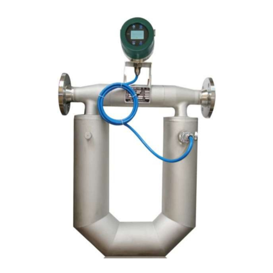
1 BCMF Mass Flow Meter Overview Befa coriolis mass flow meter (BCMF) is a new type flow meter which is designed according to Micro Motion and Coriolis principle. This kind of new flow meter can measure the fluid directly in a sealed pipeline. It consists of two sections: Sensor and Signal Transmitter. -
Page 6: Working Principle
1.3 Working Principle If a pipe is rotated around a point (P) while liquid is flowing through it (toward or away from the center of rotation), that fluid will generate an inertial force, with reference to Figure 1-1: Figure 1-1 A particle (δ... -
Page 7: Sensor Parameters
difference which is proportional to mass flow. The design of sensor is converting the measurement of Coriolis force to the measurement of phase difference for both sides of the vibrating tube. This is the working principle of Coriolis mass flow meter. -
Page 8: Technical Parameters
2.2 Technical Parameters Dimension and Measuring Range Zero Stability, kg/h Rated Specification Flow range(kg/h) Pressure (mm) (kg) (kg) 0.2% 0.15% 0.1% (MPa) BCMF-003 0~96~144 0.018 0.012 0.012 BCMF-006 0~540~810 0.099 0.066 0.066 BCMF-008 0~960~1440 0.18 0.12 0.12 BCMF-010 0~1500~2250 0.27 0.18 0.18 BCMF-015... -
Page 9: Sensor Dimension
2.3 Sensor Dimension “U” -type Integrated Model NW(only sensor) BCMF-010 BCMF-015 BCMF-020 BCMF-025 17.5 BCMF-032 BCMF-040 BCMF-050 BCMF-080 1177 87.5 9 / 35 www.befaproses.com... - Page 10 BCMF-100 1335 BCMF-150 1300 1593 1144 BCMF-200 1300 1600 1144 “U” -type Remote type Model NW(only sensor) BCMF-010 BCMF-015 BCMF-020 BCMF-025 17.5 BCMF-032 10 / 35 www.befaproses.com...
- Page 11 BCMF-040 BCMF-050 BCMF-080 87.5 BCMF-100 1115 BCMF-150 1300 1373 1144 BCMF-200 1300 1380 1144 Triangle - Integrated type Model BCMF-003 BCMF-006 70.5 BCMF-008 70.5 BCMF-010 70.5 BCMF-015 70.5 11 / 35 www.befaproses.com...
-
Page 12: Selection And Installation
3 Selection and Installation 3.1 Selection The following conditions should be considered for flow meter selection. Medium characteristics Measurability Coriolis mass flow meter is widely used for lots of fluid, but some conditions like slug flow, pulsating flow etc, where you want to install Coriolis mass flow meter, some appropriate support measures must be taken. -
Page 13: Installation
3.2 Installation 3.2.1 Basic Requirements on installation Flow direction should be in accordance with BCMF sensor flow arrow. Properly supporting is required for preventing tubes vibrating. If a strong pipeline vibration is inevitable, it is recommended to use a flexible tube to isolate the sensor from the pipe. ... - Page 14 Figure 3-2 The meter should be installed sideward when the medium is turbid liquid (Figure3-3) to avoid particulate matter accumulated in the measuring tube. The flow direction of medium goes from the bottom up through the sensor. 3. 2.3 Sensor Fixed Coriolis mass flowmeter is a vibrating instrument, when they work, the two vibrating tube is always in a state of vibration.
-
Page 15: Transmitter
4. Transmitter 4.1 Working conditions 1) Atmospheric pressure: 86~106KPa 2) Ambient temperature: LCD display: -20~+60℃; No display:-40~+85℃ 3) Relatively humidity: 35%~95% 4) Power supply: 22~245V 5) Power consumption: ≤15W 6) Communication interface: 4~20mA current loop (passive, error≤±0.005mA), Pulse 0~10KHz, RS485 4.2 Using area and Explosion This flow meter meets the requirements of Ex d ib IIC T6 Gb in GB3836.1-2010、GB3836.2—2010、GB3836.4-2010, which is suitable for Zone1, Zone2, Temperature class T6 of explosive atmospheres. -
Page 16: Terminal And Wiring
Use air plug to connect transmitter and senor (air plug protection is IP67) 4.4 Terminal and Wiring Table 4-4 show the name of terminals, Figure 4-4 show the wiring method, Current 2 have HART The 1 line signal Signal Descriptions terminals RS485+ RS485-... -
Page 17: Cable Connection
Figure 4-4 Wiring method 4.5 Cable Connection A special 9-core double shielded signal cable is used for connecting transmitter and sensor. To facilitate wiring, we provide air-plug. Structure is shown as below Figure 4-5 Cable between sensor and transmitter 17 / 35 www.befaproses.com... -
Page 18: Software Operating Procedure
4.6 Software operating procedure 18 / 35 www.befaproses.com... -
Page 19: Panel And Button
4.7 Panel and Button 4.7.1 Button function Mass flow Figure 4-7-1 Button diagram UP: move up the selection cursor DOWN: move down the selection cursor FUNC: function selection (main interface), confirm (setting interface) ESC: exit the current menu Note: The button is capacitive touch type, Use finger to touch the button to achieve the corresponding function. 4.7.2 Interface description Mass flow 19 / 35... - Page 20 Figure 4-7-2 Display interface diagram DISP #1 Any one of the following six variables can be displayed: mass flow, volume flow, total mass, total volume, density, temperature. User can set in “BASICS->DISP #1 menu”. Keyboard lock logo the keyboard has been unlocked the keyboard has been locked ...
-
Page 21: Lock And Unlock
Decimal cutoff indicate When the integer length of DISP #1 or DISP #2 is too long, the display digits will be intercepted. You can set display digits in “BASICS -> DIGITS” DISP #1 measurement value Displayed updating time and damping time set by device is the same, with reference to (10.1 damping) ... -
Page 22: Selection Function
4.9.2 Selection function Press the FUNC button to enter the selection function, you need to input password to enter BASICS and ADVANCED. 4.10 BASICS menu structure Enter the system setting menu and select BASICS, press FUNC to confirm, enter the password by direction button (initial password is 17), press FUNC to confirm and enter menu, press ESC to exit to the main interface. -
Page 23: Factory Setting Menu Structure
mA MAXVAL #2 Set data -60000~60000 (unit is the same as range) mA MINVAL #2 Set data -60000~60000 (unit is the same as range) MAX OUT FREQ Set data 0.0000~10.0000kHz FREQ OUT Option Mass flow/volume flow FREQ MAXVAL Set data -60000~60000 (unit is the same as range) FREQ MINVAL... - Page 24 Serial No. Menu Setting Method Parameters Range FLOW K Set data 0~9999.99 CAL TEMP Set data -50.0~100.0 M.FLOW MAX Set data 0~60000 Unit: t/h, kg/h, g/h M.FLOW MIN Set data 0~60000 Unit: t/h, kg/h, g/h V.FLOW MAX Set data 0~60000 Unit:m /h, L/h, mL/h V.FLOW MIN...
-
Page 25: Display Setting
N C Po2 Set data 0~150 -50~50.00 N C Po3 Set data 0~150 -50~50.00 N C Po4 Set data 0~150 -50~50.00 N C Po5 Set data 0~150 -50~50.00 SET MEMORY Option Yes/No Table 4-11 ADVANCED menu and parameters Enter ADVANCED menu and select the submenu by the UP and DOWN keys. Press the FUNC key to modify and select the parameters by the UP and DOWN keys. -
Page 26: Disp #2 Setting
Setting method for DISP #1: BASICS ->Input password -> DISP #1 setting ->Select the type of display variables ->Select the display unit. 4.12.2 DISP #2 setting Same as DISP #1 4.12.3 DIGITS DIGITS setting range is 0-3, when DISP #1 or DISP #2 automatically intercepts digits because of too long integer bits, “00” will be displayed at the upper left corner of the screen, which means the current displayed values have decimal digits to be intercepted.. -
Page 27: Small Signal Cutoff
Higher damping value makes the measurement value change significantly smoother, the change for display, current output and frequency output is slower; Lower damping value makes the measurement value change more quickly, the change for display, the current output and the frequency output is faster; Imposing higher damping value on fast and intense flow changes may result in measurement error;... -
Page 28: Flow Dir
4.13.4 FLOW DIR Flow direction will determine how the fluid forward flow and reverse flow affect the measurement value, the current output value and frequency output value. Forward flow: in accordance with flow direction arrow on the sensor; Reverse flow: in contrast to the flow direction arrow on the sensor; Flow The relation with sensor arrow The relation with displayed value... -
Page 29: 20Ma Out
Flow direction will affect the current output type only when the current output configuration at mass flow or volume flow. The effect of flow direction on frequency output Flow direction Actual flow direction setting Forward Zero flow Reverse Forward Output>0 Output=0 Output0 Reverse... -
Page 30: 20Ma Maxval And 4~20Ma Minval
4.14.2 4~20mA MAXVAL and 4~20mA MINVAL 4~20mA output mass flow: value is -60000~60000, the unit is the same as mass flow range. 4~20mA output volume flow: value is -60000~60000, the unit is the same as volume flow range. 4~20mA output temperature: value is -250~400℃. 4~20mA output density: value is 0~3000, the unit is the same as density. -
Page 31: Max Out Freq
4.15.4 MAX OUT FREQ Be used for setting the frequency value corresponding to max flow. 4.16 RESET After reset, the total mass flow and total volume flow will accumulate again. Setting method: BASICS ->Input password ->RESET-> Select yes. 4.17 ZERO CAL After installation, modify the stored zero value to the zero value which is applied to the current application, the setting method is below: 4.17.1 Preparatory condition... -
Page 32: Comm
4.18 COMM 4.18.1 COMM selection In system menu select “BASICS-Input password-COMM-Select RS485 or HART” 4.18.2 RS485 RS485 ADR: in system menu select “BASICS-input password-RS485 ADS-Input the address for the current device”, the range is 0-31 RS485 BAUD: in system menu select “BASICS-input password-RS485 BAUD-select value”, 2400/4800/9600 can be optional. -
Page 33: Debug
M.FLOW kg/h V.FLOW L/h DENSITY kg/m 2500 TEMPER ℃ TRANS MODEL TRANS SER# SN:151234 SENS SER# SN:154321 FIRMWARE VER. 00-12-34 ERROR # 4.20.2 DEBUG TEST OUTPUT Provide test function for frequency and current output. After enter this function, frequency and current output is stable value;... -
Page 34: Advanced Menu
4.21 ADVANCED menu This menu can be only set under the condition of field replacing sensor and calibration. When the device is working in the field, the parameters of this menu can not be adjusted, otherwise it may cause measurement error. 4.21.1 Flow K This coefficient can be adjusted only under the following conditions: Re-calibration... -
Page 35: Basic Fq
4.21.6 BASIC FQ Basic frequency is the parameter used for density measurement. After sensor installation, record the vibration frequency when the pipe is empty and input the value here, which is sued for the calculation of density. This is advanced setting and can not be changed.
Need help?
Do you have a question about the BCMF3100 and is the answer not in the manual?
Questions and answers