Table of Contents
Advertisement
Quick Links
Advertisement
Table of Contents

Related Manuals for Mect TP1070 Series

Summary of Contents for Mect TP1070 Series
- Page 1 USER’S MANUAL for TP1070 series HMI - Operator panel ME7032_09 06/22...
- Page 2 HMI - Operator panel: TP1070 Mect srl ME7032_09 06/22...
-
Page 3: Table Of Contents
HMI - Operator panel: TP1070 Mect srl INDEX 1. Introduction ......................1 1.1. Staff skill ......................1 1.2. Simbols ....................... 1 1.3. Terms ......................... 1 1.4. Security ......................2 1.5. REFERENCE MANUAL .................. 2 2. System description ....................3 2.1. Specification....................... 4 3. -
Page 4: Introduction
Products described in this manual are devoted to PLC programmers or automation experts only. MECT S.r.l. declines any responsibility about malfunctioning or damage caused by incorrect use of MECT devices, due to noncompliance to this manual information. MECT S.r.l has an help desk. -
Page 5: Security
HMI - Operator panel: TP1070 Mect srl 1.4. Security Attention Switch off devices before connecting them. ESD (Electrostatic discharge) Modules have electronic components that can be damaged by. electrostatic discharge. Be sure to be connected to ground when handle the devices. -
Page 6: System Description
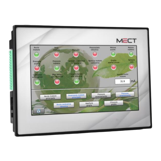
HMI - Operator panel: TP1070 Mect srl 2. System description TP1070 is a device composed by a PLC and a HMI with touch-screen monitor 7” width and 800 x 480 pixel resolution with 262.000 colors. The TP1070 operator panel allows supervision of devices connected to the Modbus TCP and Modbus RTU network. -
Page 7: Specification
HMI - Operator panel: TP1070 Mect srl 2.1. Specification The TP1070 operator panel is based on a multiprocessor system. PLC and HMI are based on a 454MHz ARM9. Table 1 Hardware characteristics Processor ARM926JE 454MHz 128MB FLASH 128MB Non volatile variables... -
Page 8: Hardware Installation
HMI - Operator panel: TP1070 Mect srl 3. Hardware Installation In the following figures see the TP1070 operator panel dimensions. 3.1. Mechanical dimensions Side view Rear view Figure 3 Figure 4 Side view Figure 5 ME7032_09 06/22... - Page 9 HMI - Operator panel: TP1070 Mect srl Technical specification Table 2 Mechanical Material Polycarbonate, Polyamide 6.6 195 mm x 145 mm x 60.5 mm Dimensions W x L x H Mounting plate 138mm x 188mm Installation Panel installation Environmental conditions Operative temperature 0 °C ...
-
Page 10: Panel Mount
HMI - Operator panel: TP1070 Mect srl 3.2. Panel mount 3.2.1. Distance System must be installed with a space for heat dissipation and cabling. Avoid cabling superimposing to avoid EMC problems. Figure 6A: Horizontal mounting Figure 6B: Vertical mounting ME7032_09 06/22... -
Page 11: Tp1070 Wiring
HMI - Operator panel: TP1070 Mect srl 4. TP1070 wiring 4.1. Connections In the following figure see the wiring diagram with the available I/O. Figure 7 Table 3 TP1070 Power Supply 12÷36Vdc Vdc 400mA USB A Ethernet Bit rate: 100Mbit/sec... -
Page 12: Power Supply
HMI - Operator panel: TP1070 Mect srl 4.2. Power supply 4.2.1. System power supply TPAC1070 operator panel has a 12÷36Vdc according to the scheme in the figure. System is protected against reverse power supply. 4.2.2. Fuse System has no internal fuse , so is suggested the use of an external 1A fuse for the panel power supply. -
Page 13: Modbus Wiring (On All Models)
HMI - Operator panel: TP1070 Mect srl 4.3. ModBus wiring (on all models) ModBus on TP1070 operator panel is a 4 wire RS485 serial line, on the M2 terminal (RTU3) board on pins: Table 4 Segnale Description 11 GND 12 TX +... -
Page 14: Canopen (Tp10070_01_B Model)
HMI - Operator panel: TP1070 Mect srl 4.4. CanOpen (TP10070_01_B model) Can interface on TP1070_01_B operator panel is on M3 terminal board on pins. Table 1 Signal CAN H CAN L GNDiso Example of a wiring of a system composed by: ... -
Page 15: Modbus Wiring (Tp1070_01_C Model)
HMI - Operator panel: TP1070 Mect srl Table 2 Baud rate Bus lenght 1 Mbit/s 10 m 800 kbit/s 50 m 500 kbit/s 100 m 250 kbit/s 250 m 125 kbit/s 500 m 50 kbit/s 1000 m Terminal resistence Inside the TP1070_01_B operator panel there is a resistance of 120... -
Page 16: Ethernet
The system can use 5472 interchange variables between HMI and automation (at maximum) which include: internal variables, interchange variables on Modbus network, retentive variables. The variables are defined by a tool furnished from Mect. 7. How to order ME7032_09 06/22...
Need help?
Do you have a question about the TP1070 Series and is the answer not in the manual?
Questions and answers