
Summary of Contents for Puretec Radfire RI-HF34
- Page 1 User Guide RI-HF34 & RI-HF75 Puretec Radfire™ Commercial UV Water Sanitiser For correct operation & installation, it is essential to observe these instructions. AUG2022...
-
Page 2: Table Of Contents
Customer Interface Wiring ......................13 Maintenance ............................13 Fig.2 - UV Reactor Parts Diagram ..................15 UV Lamp Replacement ........................ 16 Quartz Sleeve Replacement ..................... 18 UV Intensity Sensor ........................21 Installation & Operation Manual Copyright © Puretec Pty Ltd 2022... - Page 3 UV Monitoring Module ......................... 35 Remote Module ..........................47 Data Logging Module ........................50 Setting The Date & Time ......................51 Customer Interfaces ........................53 Terminal Details ..........................54 Warranty .............................. 55 Copyright © Puretec Pty Ltd 2022 Puretec Radfire RI-HF Series...
-
Page 4: Puretec Customer Service
This is a chemical free process which is simple in its concept and effective in its abilities to inactivate microorganisms present in the water supply. Simple maintenance, continuous disinfection and ultimately safe water. Puretec makes it that easy. Customer Service Helpline 1300 140 140 (Australia) 0800 130 140 (New Zealand). -
Page 5: Safety Instructions
10. Do not use this UV disinfection system for any other purpose other than disinfection of water. The use of attachments or accessories not approved, recommended or sold by the manufacturer may cause an unsafe condition. Copyright © Puretec Pty Ltd 2022 Puretec Radfire RI-HF Series... -
Page 6: System Overview
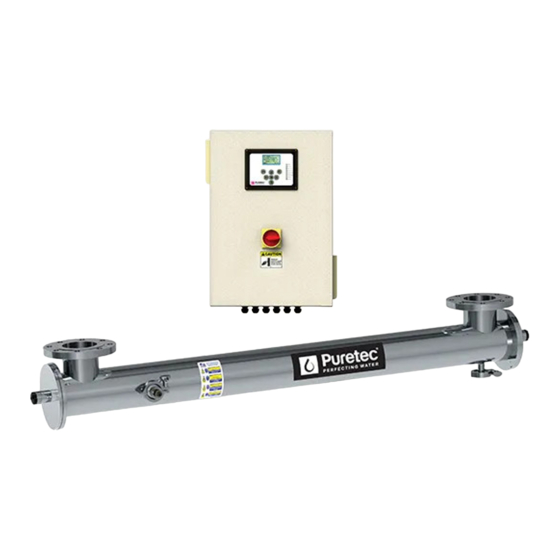
IS OUTSIDE OF THE UV CHAMBER. System Overview The Puretec RI-HF Series is designed to treat water at specified flow rates as outlined in the technical specification sheet. All units are provided with three main components, specifically the ultraviolet reactor chamber, the main control panel, and the UV intensity sensor. -
Page 7: Control Panel
UV system and a UV controller. The controller includes a 128 x 64 pixel graphical LCD display. The control panel is connected to the UV reactor via 3.5 meters of cable to allow for installation flexibility. Copyright © Puretec Pty Ltd 2022 Puretec Radfire RI-HF Series... -
Page 8: Uv Sensor
UV Sensor UV Sensor Your Puretec RI-HF Series UV system is provided with one UV sensor per unit which can measure the efficacy of the UV system in real-time and provide feedback either on the LCD or to a SCADA system via 4-20ma signal or MODBUS. -
Page 9: Factors That Affect Uv Disinfection
Any factor that affects UV light intensity or retention time will affect performance. Dose = Intensity (W/m2) x Retention Time (sec) The Puretec RI-HF Series is designed to deliver a dose that takes into account lamp aging. Quartz Sleeve Condition To ensure maximum performance from the unit, it is essential that the Quartz Sleeves be kept clean. -
Page 10: Guidelines
80%. Insulate the unit from extreme temperatures. Install the chamber horizontally (If mounting vertically first contact Puretec). To avoid trapping air, ensure the outlet is at the highest point. Allow maintenance space around the system, including the reactor length for lamp removal. -
Page 11: Installation
UV sensor installation/removal on page 33. 12. Next, plug the reactor into the appropriate electrical outlet and power up the system. 13. Follow the startup instructions in the next section. Copyright © Puretec Pty Ltd 2022 Puretec Radfire RI-HF Series... -
Page 12: System Startup
This must also be performed in case a new sensor is being fitted to the system. Follow the procedure in the section on Calibrating the UV Intensity. 12 Installation & Operation Manual Copyright © Puretec Pty Ltd 2022... -
Page 13: Customer Interface Wiring
Daily • Check the display on the UV control panel for any new errors or warning conditions. • Complete the maintenance log sheet for the day. • Check for leaks. Copyright © Puretec Pty Ltd 2022 Puretec Radfire RI-HF Series... - Page 14 Check all the O-rings. If there are indications of wear and tear (cracking or brittleness), replace the seal. Puretec recommends that the quartz sleeve sealing O-rings be replaced every time the quartz sleeve is removed/replaced in the system.
- Page 15 Cable Gland UV Reactor Drain Clamp UV Reactor Drain Blank UV Sensor UV Reactor Window Sealing Drain Gasket Gasket UV Sensor Window UV Sensor Window Clamp UV Sensor UV Sensor Window Copyright © Puretec Pty Ltd 2022 Puretec Radfire RI-HF Series...
-
Page 16: Uv Lamp Replacement
PERIOD. CYCLING OF LAMPS MAY RESULT IN PRE-MATURE LAMP FAILURE AND VOID THE WARRANTY. Use only genuine quality replacement parts from Puretec. Using any non-authorized lamps, quartz sleeve or spares in the UV system can affect the performance of the system and void the warranty. - Page 17 If the lamp is removed at an angle, pressure will be applied on the inside of the quartz sleeve, causing the sleeve to fracture and break. Copyright © Puretec Pty Ltd 2022 Puretec Radfire RI-HF Series...
-
Page 18: Quartz Sleeve Replacement
Note: Diagrams below are for representation purpose only and actual system may vary as per specific model and variant purchased. If the lamp is in the system, remove the lamp and carefully set it aside as described in the lamp removal section. 18 Installation & Operation Manual Copyright © Puretec Pty Ltd 2022... - Page 19 While holding the provided guide rod in place at the opposite end, carefully slide the sleeve out of chamber. In case it is initially tight, gently try rotating the quartz sleeve while also pulling it out. Copyright © Puretec Pty Ltd 2022 Puretec Radfire RI-HF Series...
- Page 20 UV light which will reduce the effectiveness of treatment. • Puretec SC1000 UV Sleeve/Scale Cleaner can be used for cleaning the sleeves. Steps The quartz sleeves should not be handled without gloves (use only powder free gloves).
-
Page 21: Uv Intensity Sensor
Note: Diagrams below are for representation purpose only and actual system may vary as per specific model and variant purchased. Please note that certain models and variants have a simple “screw on” type sensor window and not a tri-clamp one as shown below. Copyright © Puretec Pty Ltd 2022 Puretec Radfire RI-HF Series... - Page 22 REMOVED, ISOLATE AND DRAIN THE REACTOR CHAMBER BEFORE REMOVING THE TRI-CLAMP CONNECTOR. Now slowly remove the window from the reactor chamber. Be sure to keep the gasket in a safe place. 22 Installation & Operation Manual Copyright © Puretec Pty Ltd 2022...
-
Page 23: Control System
Control System Cleaning the Sensor Window The sensor window quartz opening should be cleaned periodically with Puretec SC1000 UV Sleeve/Scale Cleaner. Ideally this will be carried out whenever the quartz sleeve is being cleaned, but the frequency can vary by application. - Page 24 Left / Right Softkeys: These keys use used to access various features of the controller and the function of these keys changes depending on the screen / context the user is currently in. 24 Installation & Operation Manual Copyright © Puretec Pty Ltd 2022...
- Page 25 WIPER ON Not applicable in these models. LED ON: Indicates that the system is currently being REMOTE OP controlled remotely using either the REMOTE HARDWIRE option or the REMOTE MODBUS option. Copyright © Puretec Pty Ltd 2022 Puretec Radfire RI-HF Series...
- Page 26 For details on how to configure the remote mode in the remote module section. For more information on how to perform the customer end wiring to the potential free input either refer to the electrical wiring diagram or to the section titled Customer Interfaces. 26 Installation & Operation Manual Copyright © Puretec Pty Ltd 2022...
-
Page 27: Start Up
UV reactor will be placed into the running mode and the system will continue to provide full power output at all times. Once the starting mode is complete the system status will change to RUNNING as described in the next section. Copyright © Puretec Pty Ltd 2022 Puretec Radfire RI-HF Series... -
Page 28: Normal Operation
System has been turned off remotely. REMOTE OFF The user can also enter the User Setup menu from here or navigate to the different screens as shown in the User Setup section. 28 Installation & Operation Manual Copyright © Puretec Pty Ltd 2022... - Page 29 More information on this can be found in the Temperature Sensors Section. Copyright © Puretec Pty Ltd 2022 Puretec Radfire RI-HF Series...
-
Page 30: Shutdown
The UV System will also initiate a shutdown sequence for the UV Reactor in response to a Reactor (Chamber) High Temperature and/or a Control Panel (Cabinet) High Temperature. More details on this can be found in the Exceptions section of the manual. 30 Installation & Operation Manual Copyright © Puretec Pty Ltd 2022... -
Page 31: Exceptions (Warnings/Trips)
One or more lamps in the system have failed. For more information on the errors and corrective action that can be taken please refer to the section in this user guide corresponding to that module. Copyright © Puretec Pty Ltd 2022 Puretec Radfire RI-HF Series... - Page 32 System will acknowlege and return to the Home screen. Observe that now that the right softkey no longer shows ACK, but the fault is still displayed. Home Screen with Alarm Acknowledged 32 Installation & Operation Manual Copyright © Puretec Pty Ltd 2022...
-
Page 33: User Setup
Press the right softkey once to enter the SETUP menu. The software now asks for the password. Control Panel Restart Temperature Start by pressing the Left arrow key once. Parameter in the User Menu Copyright © Puretec Pty Ltd 2022 Puretec Radfire RI-HF Series... - Page 34 Then press the right arrow key once. Then press the up arrow key once. Then press the down arrow key once. Then press the left arrow key again once. Finally press the enter key once. 34 Installation & Operation Manual Copyright © Puretec Pty Ltd 2022...
-
Page 35: Uv Monitoring Module
Details screen in terms of W/m2. The UV Intensity in percentage (107%) Corresponding Absolute Intensity Displayed in the Details Screen (54 W/m2) Copyright © Puretec Pty Ltd 2022 Puretec Radfire RI-HF Series... - Page 36 User Setup section. Example of Home Screen with No Pending Acknowledgements Scroll to the UV % WARNING parameter and press the Enter key. UV % WARNING Parameter in User Menu 36 Installation & Operation Manual Copyright © Puretec Pty Ltd 2022...
- Page 37 VALUE. Calibrating The UV Intensity The UV intensity sensor requires an annual calibration, contact Puretec for details. However, whenever the lamp or sensor is replaced, the interface between the sensor and the UV controller also needs to be recalibrated. Follow the instructions to perform this procedure.
- Page 38 UV Sensor Cal Confirmation Dialog The system will now return to the user setup. Press the Right Softkey to access the Exit function and return to the Home screen. 38 Installation & Operation Manual Copyright © Puretec Pty Ltd 2022...
- Page 39 Enter key. UV Sensor Check Function in User Menu System will prompt you to confirm the calibration. Press the Left Softkey to confirm and save. Replace Lamp Parameter in User Menu Copyright © Puretec Pty Ltd 2022 Puretec Radfire RI-HF Series...
- Page 40 NOTE: DO NOT CYCLE LAMPS ON/OFF MORE THAN THREE (3) TIMES PER 24-HOUR PERIOD. CYCLING OF LAMPS ON/OFF MORE THAN 3 TIMES IN A 24-HOUR PERIOD MAY RESULT IN PRE-MATURE LAMP FAILURE AND VOID THE WARRANTY. 40 Installation & Operation Manual Copyright © Puretec Pty Ltd 2022...
- Page 41 Replace Lamp Confirmation Dialog System will now return to the user setup. Press the Right Softkey to access the Exit function and return to the Home screen. Copyright © Puretec Pty Ltd 2022 Puretec Radfire RI-HF Series...
- Page 42 Enter the User Setup menu by following the instructions in the User Setup section. Home Screen with No Pending Acknowledgements Scroll to the LAMP HISTORY parameter and press the Enter key. Lamp History Detail Record 42 Installation & Operation Manual Copyright © Puretec Pty Ltd 2022...
- Page 43 There is also a provision to restart the lamps once the temperature has dropped below the Restart Temperature setpoint. The measured temperatures, warning setpoint (W) and trip setpoint (T) can be observed on the Temperature Overview screen of the UV Controller. Copyright © Puretec Pty Ltd 2022 Puretec Radfire RI-HF Series...
- Page 44 (if any) are acknowledged and the right softkey function displays SETUP. Enter the User Setup menu by following the instructions in the User Setup section. Example of Home Screen with No Pending Acknowledgements 44 Installation & Operation Manual Copyright © Puretec Pty Ltd 2022...
- Page 45 Right Softkey to exit from the menu or change the W:CHAMBER TEMP in a similar manner to adjust the UV reactor warning UV Reactor Temperature Warning temperature setpoint. Parameter in User Menu Copyright © Puretec Pty Ltd 2022 Puretec Radfire RI-HF Series...
- Page 46 System will now display the W:CABINET TEMP dialog box. Press the Up and Down Control Panel Restart Temperature arrow key to increase or decrease the warning value. Adjustment Dialog 46 Installation & Operation Manual Copyright © Puretec Pty Ltd 2022...
-
Page 47: Remote Module
3. SCADA - with MODBUS, through a RS485 link (REMOTE MODBUS mode). To change between these three control modes one must change the REMOTE MODE parameter in the User Setup as follows: Copyright © Puretec Pty Ltd 2022 Puretec Radfire RI-HF Series... - Page 48 Local Mode Selected System will now display the REMOTE HARDWIRE option. Press the Enter key once to change the selection option if desired. Remote Hardwire Mode Selected 48 Installation & Operation Manual Copyright © Puretec Pty Ltd 2022...
- Page 49 Right Softkey to exit from the setup menus. For information about the turning the system on/off using MODBUS refer to the appendix for a complete list of MODBUS instructions. Copyright © Puretec Pty Ltd 2022 Puretec Radfire RI-HF Series...
-
Page 50: Data Logging Module
System will now display the SHOW EXCEPTIONS dialog box. It will first show the most recent lamp change. Press the Right Exception List Detail Record arrow key to move to the next record. 50 Installation & Operation Manual Copyright © Puretec Pty Ltd 2022... -
Page 51: Setting The Date & Time
User Setup section. Example of Home Screen with No Pending Acknowledgements Scroll to the SET DATE & TIME parameter and press the Enter key. Set Date & Time Menu Parameter Copyright © Puretec Pty Ltd 2022 Puretec Radfire RI-HF Series... - Page 52 Adjust Date and Time Dialog Once the time and date has been set press the Left Softkey to save and exit back to the User menu. 52 Installation & Operation Manual Copyright © Puretec Pty Ltd 2022...
-
Page 53: Customer Interfaces
Only applicable when the UV controller is used in Dose mode. 4-20 mA input signals the Flow Meter Input 4-20 mA Analog Input line flow rate input from flow meter / PLC to calculate Dose. Copyright © Puretec Pty Ltd 2022 Puretec Radfire RI-HF Series... -
Page 54: Terminal Details
4-20 mA UV Output (+) SBB34 4-20 mA UV Output (-) Display PCB (+) 4-20 mA Flow Meter Input (+) Display PCB (-) 4-20 mA Flow Meter Input (-) 54 Installation & Operation Manual Copyright © Puretec Pty Ltd 2022... -
Page 55: Warranty
Puretec’s discretion, including chargeable inspection and labour costs incurred. Warranty/Australia This warranty is given by Puretec Pty Ltd, ABN 44 164 806 688, 37-43 Brodie Road, Lonsdale SA 5160, telephone no. 1300 140 140 and email at sales@puretec.com.au.
Need help?
Do you have a question about the Radfire RI-HF34 and is the answer not in the manual?
Questions and answers