Advertisement
Quick Links
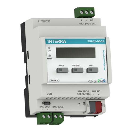
KNX-DALI Gateway
Product Code
ITR832-00X1
DALI Line Output
1 x 64, Single Channel
Max. ECG Devices
Up to 64 devices (1 x 64)
Display
2x16 LCD Display
Short-Circuit &
Available
Overvoltage Proof
Power Supply
220 V AC 50/60 Hz
Power Consumption
6 W
KNX Line Current
13 mA
Con.
DALI Line Current
1 x 250 mA
Con.
DALI Voltage
Typical 19 V DC (12...20.5)
1 x KNX, 1 x Ethernet* and
Bus Connection
1 x USB Port
Type of Protection
IP 20
Operation (-5°C...45°C)
Temperature Range
Storage (-25°C...55°C)
Max. Air Humidity
< 90 RH
Colour
Light Grey and White
90 x 70 x 64.5 mm
Dimensions
(H x W x D)
Configuration
Configuration with ETS
0 : Ethernet port | 1 : No Ethernet port
DESCRIPTION
The ITR832-00X1 & ITR832-00X2 single and dual-channel KNX-DALI
interface devices are used to provide an interface between DALI and
KNX installations, enabling communication between the two
protocols. DALI devices (ballasts, etc. ECGs) connected to the line
are supplied with the internal DALI power supply. With the
ITR832-00X1 single-channel device up to 1x64 DALI ballasts can be
connected, with the ITR832-00X2 dual-channel device up to 2 x 64
DALI ballasts can be connected. With each DALI channel, 16 groups,
16 scenarios and 64 devices can be controlled. In addition,
ITR832-00X2
independent emergency lighting according to EN 62386-202 will be
2 x 64, Dual Channel
supported with the 2nd version update. Emergency lighting tests (e.g.
Up to 128 devices (2 x 64)
function and time test) can be triggered via the KNX line. In addition,
2x16 LCD Display
feedback on the KNX line can be sent. Each DALI device can be
controlled individually, in group or broadcast control.
Available
Device Type 0 (DT0)
220 V AC 50/60 Hz
Device Type 1 (DT1)
13 W
Device Type 6 (DT6)
13 mA
Device Type 8 (DT8)
GENERAL FUNCTIONS
2 x 250 mA
•
Automatic DALI Device Addressing.
Typical 19 V DC (12...20.5)
•
1 x KNX, 1 x Ethernet* and 1
•
x USB Port
•
KNX Bus Voltage Failure Status.
IP 20
•
KNX Voltage Recovery Status.
Operation (-5°C...45°C)
•
DALI Bus Voltage Failure Status.
Storage (-25°C...55°C)
•
DALI Voltage Recovery Status.
•
Ballast and / or Lighting Error.
< 90 RH
•
Working log analysis with UDP.
Light Grey and White
•
Broadcast control can be made with manually and software.
90 x 70 x 64.5 mm
•
Tunable White color temperature control.
(H x W x D)
•
RGB and RGBW color control.
Configuration with ETS
** Please ask the Manufacturer.
COMISSIONING FUNCTIONS
•
•
•
•
•
•
•
•
SAFETY PRECAUTIONS & IMPORTANT NOTES
•
Fluorescent Lamp
Self-Contained Emergency
•
LED Lamp
Colour Control
•
•
•
•
•
•
•
•
* : ITR832-0011 & ITR832-0012 have no Ethernet port
© 2022 INTERRA
1/3
Addressing operations can be done via ETS or manual buttons as a
short address assignment.
Assigning group adressess to ballasts via ETS without need additional
software.
Faulty ballast detection.
Faulty lighting detection.
Commissioning and control via an embedded web server (**).
DALI line device selection with the manual button.
Remote software update via Ethernet connection.(*)
Emergency lighting test (according to EN 62386-202 standard).
The device may only be installed and put into operation by a qualified
electrician or authorized personnel.
For planning and construction of electric installations, the appropriate
specifications, guidelines and regulations in force of the respective
country have to comply.
Special Programming: This device is designed for professional KNX
and DALI installation. It can be programmed by ETS and Web
Browser*.
Cable Connections: Ensure making correct connections for Black and
Red wires.
Input Voltage: The input voltage shall be 240 V AC.
Installation only in dry locations and on a 35 mm DIN rail (TH 35).
For mounting, only use appropriate equipment according to
IEC 60715.
Rain, liquid and aggressive gas should not be allowed to be close to
the device.
Screw down strength is less than 0.4 Nm.
Do not get AC 240 V voltage into Bus lines, it can damage all the
devices in the system.
DS221117032GEN
Advertisement

Summary of Contents for Interra ITR832-00X1
- Page 1 DALI power supply. With the • Faulty ballast detection. ITR832-00X1 single-channel device up to 1x64 DALI ballasts can be • Faulty lighting detection. connected, with the ITR832-00X2 dual-channel device up to 2 x 64 •...
- Page 2 11. Menu Mode Button MARKS 12. Menu Setting Button 13. Menu Back Button CE : Interra KNX-DALI Gateway complies with Electromagnetic Compatibility Directive (2014/30/EU), Low Voltage Directive (2014/35/ • First, the device is pushed slightly from above in the direction of EU) and Restricting the Use of Hazardous Substances Directive the 1st numbered arrow.
- Page 3 Single Channel ITR832-00X1 : • • ITR832-00X1 - KNX-DALI Gateway Single Channel device ITR832-00X2 - KNX-DALI Gateway Dual Channel device is supplied with 240 V AC mains voltage. The phase, neutral is supplied with 240 V AC mains voltage. The phase, neutral and ground connections are shown in the figure (L, N, PE).
Need help?
Do you have a question about the ITR832-00X1 and is the answer not in the manual?
Questions and answers