
Subscribe to Our Youtube Channel
Summary of Contents for AIT CMT-SR2000N
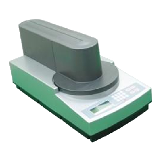
- Page 1 Operating & Service Manual CMT-SR2000N Sheet Resistance / Resistivity Measurement System...
-
Page 2: Table Of Contents
Contents Chapter 1. Specifications ------------------------------------------ 4 Chapter 2. Installation ----------------------------------------------- 9 Chapter 3. Hardware manual --------------------------------------11 Chapter 4. Software manual -------------------------------------- 16 Chapter 5. Service Manual ---------------------------------------- 39 A. Calibration ------------------------------------------ 39 B. Theory of 4-point probe & C.F---------------- 40 C. - Page 3 Product Name : Sheet Resistance / Resistivity Measurement System. Model Number : CMT-SR2000N Product Option : All Supplementary Information: The product was tested & calibrated in a typical configuration with AIT Test System. --------------------------------------------------------------------------------------------------------- www.fpp.co.kr | Tel: +82-31-695-7167 | Fax: +82-31-695-7169...
-
Page 4: Chapter 1. Specifications
Chapter 1. Specifications 1. Overview C MT- S R2 0 00 N is a f ul l a ut om at ic s ys tem t o m eas ur e s h ee t r es is tanc e a nd Res is ti v i t y f or m ax . - Page 5 4. Specifications Ø S he et r es is tanc e m eas ur em e nt . - M e as ur i n g m et ho d : Co ntac t e d b y f our p o i nt pr o be : 1 m ohm /s q ∼...
- Page 6 7. Operating software Ø G e ner a l P er s on a l c om pu t er. Ø O p er a t in g s ys t em : M ic r os oft W indo ws X P S P3 / 7 Ve r. Ø...
- Page 7 10. Measurement Flowchart Pow e r O N Sta nd b y m o de is d is p l a ye d o n t he L CD Pa n e l. O p er a t in g s oft war e ( r u n o n PC ) Lo g i n s oft war e Rem ot e m od e o n ( Loc k e d k e y o pe r a t io n i n m ac hi n e)
- Page 8 11. System Layout 12. Measurement Layout --------------------------------------------------------------------------------------------------------- www.fpp.co.kr | Tel: +82-31-695-7167 | Fax: +82-31-695-7169...
-
Page 9: Chapter 2. Installation
Ø Perform the following procedure to install this system a. Place this system (CMT-SR2000N) on a flat site without any vibration. b. Connect the power cable to AC power source (110V or 220V). c. Install CMT-SR2000NH software and Virtual Com port driver from CD. - Page 10 3. Software Installation Ø Perform the following procedure to install this system’s software. a. Operate the OS [Microsoft Windows XP SP3 / 7 Ver.] of PC. b. Insert the Installation disk into CD-ROM. c. Install Virtual Com port Driver from CD to use USB port of PC for communication. Note) The installed Virtual Com port by Virtual Com port driver will be displayed on ‘Port (Com &...
-
Page 11: Chapter 3. Hardware Manual
Chapter 3. Hardware manual 1. Hardware Operating Structure Initialize FPP Config View Ready [1] Unit [1] Ohm [2] Ohm/sq [3] Ohm.cm Thickness [4] S Thickness [2] Measure [1] Auto [2] Manual [3] Direction [1] Single [2] Dual [3] Config [1] Correction Factor [1] Circle Sample Type [2] Rectangle... - Page 12 2. keyboard Introduction a. Key 1 has its inherent own number 1 inputting function and additionally serves to move Z-axis arm downward. If Z-axis arm is down some little, X-/Y-axis are unmovable and the measurement is unavailable. b. Key 2 has its inherent own number 2 inputting function and additionally serves to move Y-axis arm toward home position only during being pushed.
- Page 13 3. Brief Measuring Method Push the Power Switch (in this system’s rear panel) to “I” position. When the electric power turns “ON”, LCD displays Fig. 1 and this system performs the initialization. After initializing, LCD displays all kinds of the defined values during some seconds, as shown in Fig. 2.
- Page 14 4. Defining Method of Configuration Pressing Mode key displays the Menu as shown in Fig 6. Set Menu 1. Unit 2. Measure 3. Config 4. Data View 5. V +/- Fig. 6 [1] Unit Unit Mode in Fig.6 can change a measuring unit into a desired unit and consists of 4 modes as shown in Fig.
- Page 15 [3] Config Consists of 3 modes (See Fig. 11). Config… 1. Correction Factor 2. Probe S Fig. 11 Correction Factor : User inputs Sample type, Thickness, TCR(Temperature Coefficient) as Fig.12 to set correction factor. The Correction Factor is generated by inputted values automatically.
- Page 16 c. TCR : User inputs Temperature Coefficient of sample. The default is 0. TCR… Def.: 0.0 [0.0000] Fig. 18 2) Probe S : This is a function to input space of probe tip. The default is 1.0mm. (See Fig. 20) Probe S…...
-
Page 17: Chapter 4. Software Manual
Chapter 4. Software manual 1. Main window 1.1 Title Bar Shows the name (CMT-SR2000NH) of current operating software, and contains Window Control buttons - Min button, Close button. 1.2 Menu Bar Each menu is activated/non-activated depending on Excess Authority of user’s level. The function of each menu is same to below Function Buttons. - Page 18 1.3.4 Remote Controls (System Eng., Config. Eng., Operator) 1) Remote ON : On/Off communication connection to controlling the instrument. Under ‘Remote On’ mode, sub menus in ‘Controls’ section is available. 2) Controls ① Zero Position : X & Y robots move onto the center of stage. ②...
- Page 19 2.3 Detail information Detailed information of user is displayed as shown in below. And user can change the password which was set by System Engineer beforehand. 2.4 Exit User should logout, and then can exit the CMT-SR2000NH software. 3. Measurement menu Select Measurement method and proceed.
- Page 20 3.1 Command menu 3.1.1 Measure (Ctrl+M) Performing measurement by selected measurement method. (Recipe mode, Extend measure mode) 3.1.2 Clear Data(Ctrl+D) Deleting all measured data only from ‘Result Sheet’ after measurement. 3.1.3 Clear All (Ctrl+A) Deleting all measured data and site after measurement. 3.1.4 Save Data (Ctrl+S) Saving the measured data after measurement.
- Page 21 u As Data Save Option is Host server or Host server and Backup Inputting ‘Input Save Item’ and applying Save, a folder “year month\machine code\” will be created automatically in Host folder path. Then, save the data as a defined file name in the created folder.
- Page 22 ② Ohm (column 2) : column 2 is a value with second unit. ex) Selected unit (column 1) Second unit (column 2) ohm/sq ohm/sq ohm.cm ohm/sq Thickness[um] ohm/sq Thickness[A] ohm/sq ③ Rohm : Resistance value transferred from machine. ④ M mode : Measure method (Single or Dual method) ⑤...
- Page 23 3.3 Extend Measure menu 3.3.1 Standard Mode Provided standard mode like Semi, Astm. (9, 13, 25point are available in rectangular S/W) 1) Semi It is a simple measuring method. It takes sample (wafer) size into account and specifies measuring points by a regular pattern. ①...
- Page 24 ASTM Measurement Point 3.3.2 Pattern Mode (not available in rectangular S/W) It specifies measuring points as many as the number of sites, in a regular angle and a distance with regard to sample size. It can measure the whole body of sample closely and regularly. 3.3.3 Cartesian Mode and Step Mode 1) Cartesian Mode : It sets measurement points with inputted X&Y interval from center position of sample.
- Page 25 ① After placing mouse pointer at an auxiliary position on Measurement window, you click the left button of mouse to set the measuring point. ② To delete a point, set block, click the “Delete Point” in Pop-up menu by click left button of a mouse on the list.
- Page 26 3.4 Analysis menu This software offers a variety of data analysis functions. 3.4.1 View Data View Data shows information of measured sample and statistics like Min, Max, AVE, StDev, Uni, Max-Min. And X, Y coordinates and measured values of each measured point are displayed in the ‘Data List’...
- Page 27 4) Close Close View data 5) View Raw Data This function will display a details of measured values like current and voltage, C.F, temperature, etc. as below. (See 3.1.7 Show detail) 3.4.2 Data Map It indicates the positions of measured points within sample pattern, and the information of sample, the statistics, the measured positions and the measured values for the sample.
- Page 28 3.4.3 Diameter Scan By referring to measured values of each points and interpolate values according to Diameter line between horizontal degree (0 ˚~ 360˚) of sample, the interpolated values are displayed with line graph. User can set the degree(min interval 1˚). 1) Deg Control User can change the degree by clicking degree button or dragging with mouse left...
- Page 29 3.4.5 3D Map 3D Map represents Contour Map in a three dimension to improve the visual effect. The comparison and interpolation method and interval line are the same as Contour Map. Also it is able to design map by using the element of 3D Map Control item.
- Page 30 5) Set Range : Refer to ‘Set Range’ in 3.4.1 View Data. 3.4.7 Trend Chart Trend Chart is able to save a Trend data(Average, Max, Min etc.) with file format. It create new file or add to saved file. This function is useful to analysis the resistance variation of sample according to the time elapse.
- Page 31 Remote Mode Indicator of Status Bar in the lower side of Main window. 3.5.2 Controls 1) Zero Position To send the moving parts (X, Y, Z axis) of CMT-SR2000N to the Zero position, click ‘Zero Position’. Note) This function is available only when Remote On.
- Page 32 3) Vacuum Mode This can be used to hold the sample on the stage. The present vacuum status is indicated in the status bar as ON or OFF. Note1) This can be used when vacuum is connected and set as Remote On. Note2) To do remote control the vacuum by using the Operating software, vacuum must be released in the system prior to Remote On.
- Page 33 1) Get from Data file. Get Trend data from saved data file. 2) Get from Current Measurement. Get Trend data from current measurement in case measured data are existed in ‘Measurement’ window. Note) This is available on ‘3.4.7 Trend Chart’. 3) Add to new Trend file / Add to opened Trend file u Add to new Trend file : Create new Trend file and add Trend data to the new one.
- Page 34 7) Save Trend File : Save Trend file. 8) Close Trend File : Close Trend file. 9) Export Trend File : Export current Trend file to Excel or Text format. 10) View. This is a function to show a graph with Trend data (Max and Min, Ave). The Ave value is default to display graph.
- Page 35 5. Configuration menu 5.1 Set Sample size (able to set the size of a sample in a rectangular S/W) When user enters each of items and clicks ‘Set Sample’ button, the shape of test sample is changed according to the entered (specified) values. User can change grid in the ‘Sample Display’ field that is displayed a sample shape in the ‘Measurement’...
- Page 36 5.1.1 Load When measuring various kinds of Samples, user selects Sample Type stored to set the size of sample and the related information. Sample Type and the related information currently stored are indicated in ‘Sample List’ item. 1) Load After selecting record with block function, clicks the ‘Load’...
- Page 37 5.2 Edit Recipe 5.2.1 Command menu 1) Open Recipe File Opening a recipe file saved. The location of opened file is displayed on ‘Recipe File’ item. 2) Save Recipe File Saving the measurement points and Sample size, information to recipe file. 3) Clear Points All Clear all points except sample size.
- Page 38 2) Points setting by Mouse Place the mouse pointer on the ‘Edit Recipe’ field, and click left button of mouse pressing the left shift button of keyboard, then a point will be created on the clicked place. And the point will be added on the new row of ‘Points List’...
- Page 39 ② Set Para Setting each variables required to auto calculate correction factor. a. Probe Pin Space Input the space of pin (mm). b. Temperature Coefficient of Resistivity The temperature coefficient of sample is directly entered by the user. If user does not input the temperature coefficient or it is ‘0’, the factor for temperature compensation will be just ‘1’...
- Page 40 ② Interpolation Resolution Set default resolution of the interpolation for Contour and 3D map. Measurement Method This function is to select Single or Dual Measurement Method. Note) Please refer to Four Point Measurement Theory for details of Measurement Method. 6. System Environment menu 6.1 Environment 6.1.1 Measurement Option 1) Error Process...
- Page 41 It is able to select the current source Range, the Direction of current flowing and Typical Applications. 1) Range : Current range is Auto only. 2) Direction : Selecting current flowing direction. It’s only ‘both’ 3) Typical Application : Selecting sample type (CMT-SR2000N restricted for wafer only). --------------------------------------------------------------------------------------------------------- www.fpp.co.kr | Tel: +82-31-695-7167 | Fax: +82-31-695-7169...
- Page 42 Note) When the measurement is completed with the retry times, stop retry. 6.1.6 Rs-232 Port It selects a communication port (RS-232C) of PC for the remote control of CMT-SR2000N. The default value is Com1. Note) In case of using USB port of PC, the ‘Virtual Com port’ driver should be installed on PC.
- Page 43 6.2 User Management Adding or deleting User ID who will use Operating software. 6.2.1 User Add 1) User ID : User’s ID (8digits of character) 2) Password : User’s Password 3) Level : There is limitation to use the program according to the level, so that important values or setting can be remained.
-
Page 44: Chapter 5. Service Manual
Resistance Standard 3” Wafer of VLSI Incorporation Ltd. When this system has a measuring error of more than 1%, please contact the seller or AIT Co., Ltd. to calibrate this system. A much worn probe should be replaced or repaired as damaging this system. -
Page 45: Theory Of 4-Point Probe & C.f
B. Theory of 4-point probe & C.F. 1. Purpose To determine the Resistivity of a substrate or a thin film by using the four point probe, current source. This SOP also determines the conductivity using the four-point probe. 2. General Instructions and Precautions The probe tips are a very critical part of the four-point probe and great care should be taken when using the equipment. - Page 46 Ø Four Point Probe Schematic t(Coating Thickness) D (Sample Diameter) Ø Sample Size Correction Factor (C.F.1) Rectangle Rectangle Rectangle C.F.1(d/s) Circle Square L/W=2 L/W=3 L/W=4 0.9988 0.9994 1.25 1.2467 1.2248 1.4788 1.4893 1.4893 1.75 1.7196 1.7238 1.7238 1.9475 1.9475 1.9475 2.3532 2.3541 2.3541...
- Page 47 Sample Thickness Correction Factor (C.F.2) C.F.2(t/s) F (t/s) < 0.4 1.000 0.400 0.9995 0.500 0.9974 0.555 0.9948 0.625 0.9896 0.714 0.9798 0.833 0.9600 1.000 0.9214 1.111 0.8907 1.250 0.8490 1.429 0.7938 1.667 0.7225 2.000 0.6336 Temperature Correction Factor Table (C.F.3) Note) approximate values for Silicon.
-
Page 48: Center Position Calibration Method
C. Center position Calibration Method 1. After the hardware is ready to start the operation, press [Enter + ESC key] on its membrane. The following message appears on LCD screen. Motor set. 1] X-axis 2] Y-axis 3] Z-axis 2. Press 2-key to select y-axis. The following message appears. Set y-axis 1] Accelerate Block 2] Speed... -
Page 49: Service
Check if a test sample is suitable to a current probe head? (Refer to “Probe selection guide” in Next page) When you find out something wrong except above check-points, please contact the seller or AIT Co., Ltd. 2. Symbol ~ : Alternating current... -
Page 50: Probe Head Selection Guide
E. Probe Head Selection Guide --------------------------------------------------------------------------------------------------------- www.fpp.co.kr | Tel: +82-31-695-7167 | Fax: +82-31-695-7169...
Need help?
Do you have a question about the CMT-SR2000N and is the answer not in the manual?
Questions and answers