Advertisement
Quick Links
Advertisement

Related Manuals for Nohken FQ

Summary of Contents for Nohken FQ
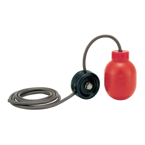
- Page 1 TS02-0182 INSTRUCTION MANUAL CABLE SUSPENDED FLOAT SENSOR MODEL: FQ Revision 2019-11-15...
- Page 2 ・The specification of product mentioned in this manual may not be satisfied by the condition of environment and usage. Check and consider carefully before using. ・Contact to sales office at NOHKEN INC. for any question or comment about this manual and product.
- Page 3 (Follow the additional document and/or direction, submitted by NOHKEN INC. and our distributor or agent.) Turn off the power, before wiring and inspection. Otherwise, electric leakage, fire caused by short circuit, and electric shock may be occurred.
- Page 4 CAUTION Check and deeply consider the chemical compatibility for material of product in advance. The part especially float, which is very thin, may be malfunctioned by miner corrosion. Check and deeply consider the chemical compatibility for material of product in advance. Hold the stem very close to mounting point, when carrying, installing, and removing.
-
Page 5: Warranty And Disclaimer
B) We are glad to suggest and advice for Model selection and chemical resistant of material, but final decision has to be made by the customer. C) This manual has prepared with close attention. Ask sales office at NOHKEN INC. for any question or comment about the contents of this manual. -
Page 6: Specifications
TABLE OF CONTENTS Page No. 1. PURPOSE OF USE ・・・・・・・・・・・・・・ 1 2. SPECIFICATIONS ・・・・・・・・・・・・・・ 1 2.1 Model ・・・・・・・・・・・・・・・・・ 1 2.2 Standard Specifications ・・・・・・・・ 1 2.3 Outline drawing ・・・・・・・・・・・・ 2 3.OPERATING PRINCIPLE ・・・・・・・・・・・・ 3 4.COMPONENT NAMES ・・・・・・・・・・・・・・ 4 4.1 External parts ・・・・・・・・・・・・・ 4 4.2 Terminal box internal parts ・・・・・・... - Page 7 2. SPECIFICATIONS 2 . 1 M o d e l N O T E : In case of a part of sensor, model are FQ-6, FQ-8 or FQ-8T. 2 . 2 S t a n d a r d s p e c i f i c a t i o n...
- Page 8 2 . 3 O u t l i n e d r a w i n g Fig. 1 Model F Q - 6 Fig. 2 Model FQ-8 & FQ-8T Fig. 3 Model FQ88-1 - 2 -...
- Page 9 3 . O P E R A T I N G P R I N C I P L E In case of rising level, the float rises according to liquid level as shown Fig. 4(1) and turns over quickly on upper limit level of control width. Movable weight travels from top to bottom inside the float and touch with permanent magnet.
- Page 10 5 . 1 U n p a c k i n g The Quick Float Model FQ series have been thoroughly inspected and carefully packed at the factory to prevent from damage during shipment. When unpacking, exercise due care not to subject the instrument to mechanical shock.
- Page 11 5 . 2 A s s e m b l y Usually, the Quick Float is set specified measuring length before shipment. When not specified, each parts are packed severally. In that case, proceed to assemble as follows. (1) Fasten one end to the eyebolt on flange and the anchor weight to another end of rope according to depth of the tank.
- Page 12 (b) In case of ↓ OFF setting. Fig. 10 (c) In case of upper and lower limit control. Fig. 11 N O T E the following points ; (1) Cable free length means length from bottom of float to clip set point. (2) Setting value of control width are 0.27 to 1 m at Model FQ66, 0.33 to 4 m at Model FQ88 and FQ88T.
- Page 13 (3) Tighten the bushing not to loose and not to move the cable. (4) Bundle the cable and the rope with band. (5) Cut the useless part of cable and install compression terminals fitted to M3.5 screws to the end of lead wires. (6) Connect each lead wires to the terminals.
- Page 14 6 . W I R I N G Fig. 15 denotes wiring of internal terminal box. N O T E the following points ; (1) Install compression terminals fitted to M3.5 screw to the inner conductor. (2) The cable inlet must be properly fitted to preserve the protection category IP45 and to protect the sensor from rain, splashing water, and so on.
- Page 15 N O T E the following points: ( 1 ) Do not connect the plural relay unit to identical switch. Otherwise, the relay unit may be malfunction. Fig. 17 ( 2 ) Power supply must be connected in phase. Fig. 18 ( 3 ) To avoid malfunction, the wiring distance should be used within specifications.
- Page 16 In assessing corrosion, key factors are concentration, liquid’ s temperature and the amount of time the sensor immersed. Please check them. ※2 Reed switch was damaged over current by miswiring, re-wire correctly. If above remedies are unsuccessful, ask NOHKEN INC. to repair and replace. - 10 -...
- Page 17 OSAKA HEAD OFFICE : 15-29 Hiroshiba-cho, Suita, Osaka 564-0052, Japan TEL: 81-6-6386-8141 FAX: 81-6-6386-8140 TOKYO HEAD OFFICE : 67 Kandasakumagashi, Chiyoda-ku, Tokyo 101-0026, Japan TEL: 81-3-5835-3311 FAX: 81-3-5835-3316 NAGOYA SALES OFFICE: 3-10-17 Uchiyama, Chikusa-ku, Nagoya, Aichi 464-0075, Japan TEL: 81-52-731-5751 FAX: 81-52-731-5780 KYUSHU SALES OFFICE: 2-14-1 Asano, Kokurakita-ku, Kitakyushu, Fukuoka 802-0001, Japan TEL: 81-93-521-9830...
Need help?
Do you have a question about the FQ and is the answer not in the manual?
Questions and answers