
Summary of Contents for Flight Sounds FUSION-GA
- Page 1 User Manual for Flight Sounds Products: FUSION-GA / 1A~1B ● FUSION-HM / 1A~1B ● 2022-12-11 © 2022 FLIGHT SOUNDS LTD, all rights reserved www.flightsounds.com Page 1 of 37...
-
Page 2: Table Of Contents
1. Contents Contents ............................2 Important Information ........................3 Product Overview ..........................4 3.1. Description 3.2. Requirements 3.3. Product Items Supplied 3.4. Key Features and Specifications 3.5. Product Version Set-up Guide ............................ 7 4.1. Operating Set-Up — Windows 11 4.1.1. Basic Setup 4.1.2. -
Page 3: Important Information
● Only use within the specified Operating Temperature of -15˚C to 70˚C. ● NB: It is advised to plug in Flight Sounds FUSION before launching any software programs you intend to use it with. -
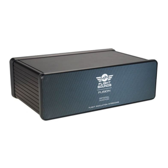
Page 4: Product Overview
3. Product Overview 3.1. Description Flight simulation will never be ‘as real as it gets’ unless it sounds and feel authentic. The Flight Sounds FUSION product helps to achieve this goal by bringing flight simulation audio into the 21 century. -
Page 5: Key Features And Specifications
- via Flight Sounds PTT Auxiliary Module (Sold separately), and/or - via 3rd party game controllers NB: In both instances PTT support requires the Flight Sounds PTT Mapper Software (Sold separately) - PTT settings for sidetone, intercom link, and computer audio Technical Specifications: ●... -
Page 6: Product Version
3.5. Product Version ● This User Manual applies only to Flight Sounds - FUSION model numbers “1A~1B” as indicated on the Model number sticker on the Product (if included on the product) Page 6 of 37... -
Page 7: Set-Up Guide
● Follow these steps to set up the Flight Sounds FUSION for use with Windows OS. Step 1: Connect one end of the USB cable (supplied) to the Flight Sounds FUSION and the other end to an available USB port (or hub) on the computer. After the Flight Sounds FUSION is connected to the computer, the standard Windows OS driver installs automatically to the computer. - Page 8 Step 3: Select the Playback tab and confirm the Flight Sounds - FUSION as the default playback device, as shown in Figure 4.1 Sound - Playback Tab. Figure 4.1 Sound - Playback Tab Step 4: Select the Recording tab and confirm the Flight Sounds - FUSION as the default recording device, as shown in Figure 4.2 Sound - Recording Tab.
-
Page 9: Volume And Mute Settings
Step 1: Open the Sound options from the Control Panel (Start → Control Panel → Hardware and Sound → Sound) Step 2: (i) Select the Playback tab and (ii) open the Headphone properties of the “Flight Sounds - FUSION” and (iii) select Levels tab, as shown in Figure 4.3 Headphones Properties - Levels Tab. - Page 10 Step 1: Open the Sound options from the Control Panel (Start → Control Panel → Hardware and Sound → Sound) Step 2: Open the microphone properties of the “Flight Sounds - FUSION” from the Sound options and select Levels tab, as shown in Figure 4.4 Microphone Properties - Levels Tab.
- Page 11 Step 1: Open the Sound options from the Control Panel (Start → Control Panel → Hardware and Sound → Sound) Step 2: (i) Select the Recording tab and (ii) open the Microphone properties of the “Flight Sounds - FUSION” and (iii) select Custom tab, as Figure 4.5 Sound Recording / Mic properties / Custom tab illustrates.
-
Page 12: Operating Set-Up - Macos 13.0
Basic Setup Step 1: Connect one end of the USB cable (supplied) to the Flight Sounds - FUSION product and the other end to an available USB port (or hub) on the computer. After the Flight Sounds - FUSION product is connected to the computer, the standard macOS driver installs automatically. - Page 13 Figure 5.1 Input Tab - Flight Sounds FUSION Figure 5.2 Output Tab - Flight Sounds FUSION Page 13 of 37...
-
Page 14: Volume And Mute Settings
Step 1: Open the System Preferences from the Apple menu. Open the Sound options from the System Environment settings. Step 2: Select the Input tab and confirm the “Flight Sounds - FUSION” as the recording device as shown in Figure 5.1 Input Tab - Flight Sounds FUSION. -
Page 15: Peripherals: Cables, Connectors, Controls, Switches Preparation
6. Peripherals: Cables, Connectors, Controls, Switches Preparation Your Flight Sounds FUSION product comes with all the Peripherals (cables, connectors, controls, and switches) you need. The exact Peripherals depend on the model. Initially, the Connectors, Controls, Switches come joined together on two larger Printed Circuit Boards (PCBs). - Page 16 FUSION-GA: Instructions Step 1: Remove the larger PCB which has the Audio Connectors and Switch Figure 6.1 Larger PCB with Connectors - unbroken Step 2: Carefully flex the end of the PCB back and forth – where it says “Break Apart Here” [on the underside] until the PCB breaks into a smaller PCB.
- Page 17 Step 3: Repeat Step 2 until the entire large PCB is broken into smaller PCBs Figure 6.3 Connector PCB - correctly broken apart Step 4: Repeat Steps 1-3 for the (Volume/Squelch) Control PCB Figure 6.4 Volume control PCBs - unbroken (above) and broken (below) Page 17 of 37...
- Page 18 FUSION-HM: Step 1: Remove the larger PCB which has the Audio Connectors and Switch Figure 6.5 Larger PCB with Connectors - unbroken Step 2: Carefully flex the end PCB back and forth – where it says “Break Apart Here” [on the underside] until the PCB breaks into a smaller PCB.
- Page 19 Step 3: Repeat Step 2 until the entire large PCB is broken into smaller PCBs Figure 6.7 Connector PCB - correctly broken apart Step 4: Repeat Steps 1-3 for the (Volume/Squelch) Control PCB Figure 6.8 Volume control PCBs - unbroken (above) and broken (below) Page 19 of 37...
-
Page 20: Peripherals: Wiring And Testing
7. Peripherals: Wiring and Testing 7.1. Wiring Diagram Connect the wiring as per the image below and by following the Wiring Instructions (Section 7.2). Ensure all the connections are made firmly. LINK EXTENSION CABLES (2m) are available* – should extra cable length be required for any of the cables. -
Page 21: Wiring Instructions
Note: In all instances – ensure that all cable plugs are firmly inserted into their respective sockets. ● Step 1: Port - USB Connect: o Firmly One end of the USB cable to the Flight Sounds FUSION ▪ The other end to a computer ▪... - Page 22 ● Step 4: Port: VOLUME / SQUELCH (Channel 1) o Firmly Connect: Flight Sounds FUSION ▪ One end of the LINK Cable to the port labelled “VOLUME / SQUELCH (Channel 1)” ▪ The other end of the LINK CABLE to the LINK SPLITTER CABLE o Step 4a: Volume ▪...
- Page 23 ● Step 6: Port: HEADSET AUDIO (Channel 1) o Firmly Connect: Flight Sounds FUSION ▪ One end of the LINK Cable to the port labelled “HEADSET AUDIO (Channel 1)” ▪ The other end of the LINK CABLE to the LINK SPLITTER CABLE o Step 4a: Volume ▪...
-
Page 24: Testing Instructions
● Aviation Headsets are connected – including Microphone and Headphone aspects ● Flight Sounds FUSION is connected to a computer which is turned on. ● Also: Ensure all Switches on the REAR PANEL are off (ie: In the Down position) ●... -
Page 25: Peripherals: Installation
8. Peripherals: Installation In order to mount the Controls, Connectors and Switch into a panel – refer to the following cut-out dimensions: 8.1. Cut-out: Audio connector The required cut-out dimension for the microphone and headphone connectors is: Ø 10.2mm ● Drawing not to scale Figure 8.1 Panel Cut-out dimensions - Audio Connectors 8.2. -
Page 26: Cut-Out: Switch / Led
8.3. Cut-out: Switch / LED The required cut-out dimension for the Switch and LED is: 20mm (L) x 13 mm (W) [Switch Cut out] Ø 3.2mm [LED hole Cut out] ● Notes: o Drawing not to scale. o Lines shown are centre to centre Figure 8.3 Panel Cut-out dimensions - Power Switch and LED 8.4. -
Page 27: Installation
● You may choose to mount your own Knobs – in a style of your choosing. ● Alternatively, Flight Sounds sells Knobs which can be used for your installation. Potentiometer control knobs are available* from Flight Sounds should they be required. (*Sold separately from flightsounds.com) - Page 28 Mounting Brackets ● Flight Sounds sells Mounting Brackets for the Flight Sounds FUSION which provide a robust and tidy solution to mounting the product in a location of your choosing. ● The mounting brackets feature a reversable design – meaning that they can secure the Product to the topside or underside of (say) a desk.
-
Page 29: Rear Panel - Cable Connections
2. Intercom link (Out) - Type: 3.5mm TRRS socket - Connect To: Intercom Link (In) on other DUAL / FUSIONs using Flight Sounds - Intercom Link Cable (Sold Separately) - Function: Intercom Link enables multiple devices to be connected – enabling a large multi- channel intercom. - Page 30 5. AUX IN (Device) - Type: 3.5mm TRRS socket - Connect To: Smart phone or equivalent using Flight Sounds - Intercom Link Cable (Sold Separately) - Function: Enables the intercom to connect to (say) a Smart Phone. The Phone is able to receive the intercom sounds and also play sounds (eg: Music) to the Intercom.
- Page 31 - Connect To: Flight Sounds PTT Auxiliary Module (Sold Separately) - Function: Via the Flight Sounds PTT Auxiliary Module – the feature enables the users to wire their own PTT Switches, to control various PTT features of the Flight Sounds – FUSION.
- Page 32 Type: 3.5mm TRRS socket - Connect To: The small PCB labelled “POWER” – via the LINK CABLE (Both Supplied) - Function: The feature enables the users to wire their own Power Switch for the Flight Sounds – FUSION. Page 32 of 37...
-
Page 33: Rear Panel - Settings
10. Rear Panel – Settings The Flight Sounds FUSION has provision for x6 real panel settings. These are outlined as below: Referring to Figure 8.1 FUSION - Rear Panel Settings the following connections are listed from 1 to 6. Figure 10.1 FUSION - Rear Panel Settings Notes: For all settings Users shall move the switch to the up position to turn that particular function ON. - Page 34 1: Stereo H/S Audio ● Full wording: Stereo Headset Audio ● Description: - Turn setting ON to enable stereo audio to the headsets. - Turn setting OFF to revert to mono audio 2: Non-Aviation H/S ● Full wording: Non-Aviation Headsets ●...
- Page 35 - Turn setting ON to enable PTT. Specifically, this will enable users “transmit” their intercom audio to another Flight Sounds (DUAL/FUSION) Intercom only when a valid* PTT event occurs. - Turn setting OFF to continuously ‘transmit’ the intercom audio to another Flight Sounds (DUAL/FUSION) Intercom.
-
Page 36: Troubleshooting Guide
11. Troubleshooting Guide If you are experiencing some issues with the Flight Sounds FUSION we would encourage you to read through this Trouble Shooting Guide. Please also review the FAQs on the Flight Sounds website. Device will not turn on Ensure Device in plugged into a computer;... -
Page 37: Technical Support And Contact Info
● The user assumes all responsibility and liability for proper and safe handling of the device. Further, the user indemnifies FLIGHT SOUNDS from all claims arising from the handling or use of the device. ● Except to the extent of the indemnity set forth above, neither party shall be liable to the other for any indirect, special, incidental, or consequential damages.
Need help?
Do you have a question about the FUSION-GA and is the answer not in the manual?
Questions and answers