
Related Manuals for Sfere WDH-31-531

Summary of Contents for Sfere WDH-31-531
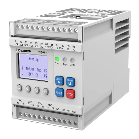
- Page 1 Motor Protection Controller User Manual Applied to: WDH-31-531 JIANGSU SFERE ELECTRIC CO., LTD.
-
Page 3: Table Of Contents
CONTENT 1 Introduction ...................... 1 1.1 Product Overview ..................1 1.2 Application scenario ................3 1.3 Overview of functions ................5 1.3.1 Monitoring functions ..............5 1.3.2 Protection functions ..............6 1.3.3 Control functions ................7 1.3.4 Communication ................7 1.3.6 Management functions ..............9 1.4 Overview of system components ............11 1.5 Order codes .................. - Page 4 3.8 Ground Fault ..................24 3.9 Residual Current .................. 25 3.10 Start Overtime ...................26 3.11 Phase sequence ................. 27 3.12 Under Voltage ..................27 3.13 Over Voltage ..................28 3.14 Voltage Imbalance ................29 3.15 PT Breaking ..................29 3.16 External Fault ..................30 3.17 Time tE ( Increased Safety Motor ) ...........31 3.18 Thermistor ..................
- Page 5 5.1.2 Interface definition ..............44 5.1.3 Related parameters ..............44 5.1.4 Modbus instruction sets ............45 6. Operation panel .....................46 6.1 Panel ....................46 6.2 Control interface ..................47 6.3 Query interface ..................48 6.3.1 Running data ................49 6.3.2 Alarm ..................50 6.3.3 Record ..................50 6.3.4 Maintenance information ............51 6.4 Setting interface ..................
- Page 6 Version Date Description number V1.0 2022.04.22 Initial version V1.1 Correct some errors 2022.06.15 Precautions This instruction is intended for use by professionals who are trained and familiar with standards in electrical installation and control and automation engineering. The responsible person must ensure that the application or use of the product meets all safety requirements.
-
Page 7: Introduction
1 Introduction 1.1 Product Overview WDH-31-531 motor protection controller (hereinafter referred to as controller or WDH) is applicable to the application sites of three-phase low-voltage AC motor with rated frequency of 50/60hz, rated voltage of 690V AC and rated current of 800A. The product has the functions of monitoring, control, protection and communication, and provides perfect protection and control for the motor. - Page 8 - Equipped with upper computer management software to realize parameter configuration, debugging and monitoring - Modular structure design, flexible combination of main body, transformer, display module and optional function - The installation method is flexible and the overall size is reasonable. It can be installed in 1 / 4 drawer cabinet...
-
Page 9: Application Scenario
1.2 Application scenario Breaker Fuse Voltage inputs Voltage Contator METERING V,A,W,Var,VA,pf,Hz,Wh,Varh Current inputs Phase CT 3 Residual inputs 50G 51G Residual CT1 Thermistor inputs LOAD MOTOR RS485-Modbus RTU Figure 1 WDH-31-531 Function block diagram... - Page 10 Monitoring + Protection Start/Stop + Monitoring Remote control + Monitoring Modbus-RTU FU3 FU4 FU5 Panel Stop Start Run Alarm Fault START START STOP RESET PTC/NTC AO1+ AO1- DIC DI1 DI2 DI3 DI4 DI5 ~ 3 M Figure2 WDH-31-531 Typical application diagram...
-
Page 11: Overview Of Functions
Power Factor ( PF) 1.0% / 0.001 0 ~ ±1 Active energy ( EP ) 2.0% / 0.01kWh Reactive energy ( EQ ) ---/ 0.01kvarh Motor Thermistors (PTC / NTC) 3.0% / 0.01 kΩ 0 ~ 10kΩ temperature Table 1. WDH-31-531 Measuring parameter... -
Page 12: Protection Functions
Current imbalance Phase loss Short Circuit 50/51 Ground Fault 50N/51N Residual Current 50G/51G Start overtime time tE Voltage Under voltage 27/27P Over voltage Phase sequence Voltage imbalance PT breaking Non- Thermistor electric External fault Table 2.WDH-31-531 Protection overview & ANSI code... -
Page 13: Control Functions
1.3.3 Control functions * WDH-31-531 by the main control module to achieve the control of the motor stop/start. * Main module contains 5 DI, 4 relay output and 2 analog ouput * By simple programming to achieve the logical control as following: Motor start type Uncontrolled :... - Page 14 Interlocking stop signal input (no control permission limit) External Fault External fault signal input, can be connected to non-electrical sensors, relays, etc. L/R Switch Local, remote control permission switching signal input, generally connected to the switch Table 5. WDH-31-531 DI common functions...
-
Page 15: Management Functions
Motor alarm status signal output Total trip signal Motor fault status signal output Table 6. WDH-31-531 Relay common functions 1.3.6 Management functions The data management of the motor protector is accomplished by the main control module and could be record the relative data by the display module or the communication interface. - Page 16 ·12 times DI Switch Record ·12 times Reset Record Table 7. WDH-31-531 Management functions overview...
-
Page 17: Overview Of System Components
1.4 Overview of system components Components Image Descriptions Special protective type current transformer Hole type(25A) -Three phase current measurement access 5A (0.2A~5A) -It must be installed integrally 25A (2.5A~25A) with the main body (splicing type) -100A current perforated access -If the circuit current exceeds Hole type(100A) 100A, an external primary 100A (10A~100A) - Page 18 SHI-ZT60 ··External CT is inevitable for (core size: 60mm) the current of the main loop is over 100A · SHI-ZT60 (300A:5A) · SHI-ZT60 (500A:5A) · SHI-ZT60 (800A:5A)
-
Page 19: Order Codes
1.5 Order codes WDH-31-531 Rated voltage: AC380V AC660V AC100V Rated current: 100A 300A 500A 800A Type selection by rated current Code Range Motor Power(380VSystem) Hole size Φ10.5mm 0.2A~5A 0.13~2kW Φ10.5mm 5A~25A 2~11kW 100A Φ18mm 25A~100A 11~55kW 250A Φ10.5mm 100A~250A 45~115kW( External CT 300A:5A) 500A Φ10.5mm... - Page 20 Mode Selection Example WDH-31-531 -25A/380V WDH-31-531 -100A/660V + T Protocol 1*Modbus 1*Modbus rated current 25A (5A~25A) 100A (25A~100A) rated voltage AC380V AC660V DC24V(Passive contact point) DC24V(Passive contact point) Additional function None 1*thermistor input...
-
Page 21: Installation
2. Installation 2.1 Size 2.1.1 Controller main body installation(5A/25A hole type) 2.1.2 Controller main body installation(100A hole type)... - Page 22 2.1.3 Display panel Module installation SHI-ZT40 ( hole size 40 x 30 ) SHI-ZT60 ( hole size 60 x 40 ) 62.5...
-
Page 23: Terminal Wiring
2.2 Terminal Wiring 2.2.1 Diagram of connection between main body and display panel Function Terminal Sign Description Power supply input (L / +) Power supply input Power supply input (N/ -) Phase A voltage input Voltage measurement Phase B voltage input input C phase voltage input Zero line voltage input... -
Page 24: External Residual Current Transformer Wiring
AO1- Analog output(-) Analog output AO1+ Analog output(+) PT100 input PTC/NTC Thermal resistance input #1- RS485-Modbus A Communication output #1- RS485-Modbus B 2.2.2 External residual current transformer wiring ZT40 ZT40 ZT40 2.3.3 Voltage input wiring 3P4W 3P3W 1P2W... -
Page 25: Motor Protection
3. Motor protection 3.1Thermal Overload The thermal overload protection is monitoring the motor heating status by stimulating the motor heat capacity under star/running circumstance so as to eliminate the motor repetitive start under over heat for ensuring the motor running in normal circumstance. Thermal overload protection provides 12 inverse-time protection curve (trip class), comforts to IEC 60947-4-1. - Page 26 Overload Alarm/ Trip & Starting Motor status: Running Record T: Trip Time I: M ax Cur rent T≥ Iq:Startup Cur rent (I/Iq) K: K R atio for cu rve Figure 2.Overload protection logic Parameters Range Defaults Protection Enable OFF / Alarm/ Trip / Alarm&Trip Alarm&Trip Startup current 100%Ie...
-
Page 27: Stall
3.2 Stall Stall protection is the time-limited current protection during start-up, and automatically exits after the start. I: M ax Current Iset:Alarm/ Trip Level Stall Tset:Trip Delay Time Trip Tset & Motor: S tarting Record I > Iset Alarm Figure 3.Jam protection logic Parameter Range Default... -
Page 28: Phase Loss
Trip Delay-starting 5.0s 0.1s ~ 600.0s Trip Delay-running 3.0s 0.1s ~ 600.0s Table 10.Current unbalance protection related parameters 3.4 Phase Loss Phase loss is an extreme expressive of the current imbalance. It cause serious heating of the rotor to burn and damage the motor. It accounts 30% of the motor damage by phase loss. Phase Loss Tset:Trip Delay Time Starting... -
Page 29: Jam Protection
I: M ax Current Iset:Current Alarm/ Trip Level Pset:Power Alarm/ Trip Level UnderLoad Tset:Trip Delay Time Trip Tset & Motor status: Running Record I < Iset Alarm P < Pset Figure 6.Under load protection logic Parameter Range Default Protection enable OFF/ Alarm / Trip/ Alarm&Trip Under load type Current / Power... -
Page 30: Short-Circuit
3.7 Short-Circuit Short-circuit protection preventing oversize fault current damage the motor. If the trip object refers to the circuit breaker, the controller will break the circuit breaker (instantly) when short-circuit was happened and break the contactor after 500ms. I: M ax Current Iset:Trip Level Tset:Trip Del ay Time Short Ci rcuit... -
Page 31: Residual Current
3I : 3 * Zero sequnece Iset:Alarm/ Trip Level Ground Fault Tset:Trip Delay Time Trip Tset Starting & Motor status: Running Record > I Alarm Figure 9.Single-phase ground fault protection logic Parameter Range Default Protection enable OFF / Alarm / Trip / Alarm&Trip Alarm Level 40%Ie 20%Ie ~... -
Page 32: Start Overtime
Trip delay-running 0.5s 0.0s ~ 600.0s Trip object Breaker Contactor / Breaker Table 16.Residual Current protection related parameters 3.10 Start Overtime Start over time protection will be implemented when proceeding start and exit from motor running automatically. The start overtime protection will be proceed when it detected the current is less than 10%Ie or more than the setting delay-running time after the start motion. -
Page 33: Phase Sequence
3.11 Phase sequence Phase sequence will cause motor reversal Phase Reversal Tset:Trip Delay Time Trip Tset Starting & Motor status: Running Record Phase angle er ror Alarm Figure 12.Voltage phase sequence protection logic Parameter Range Default Protection enable OFF / Alarm / Trip Trip delay time 3.0s 0.0s ~... -
Page 34: Over Voltage
Tripping object Breaker 0.1s ~ 600.0s Contactor / Breaker Table 19.Under voltage protection related parameters 3.13 Over Voltage Over voltage will cause motor isolation damage Umax:Max Voltage Uset:Alarm/ Trip Level Over Voltage Tset:Trip Delay Time Trip Tset & Motor status: Running Record Umax >... -
Page 35: Voltage Imbalance
3.14 Voltage Imbalance Grid voltage instability will cause reduction of the motor rotation speed and stop running consequently. Umax:Max Voltage Imbalance voltage Umin:Min Voltage Pset:Alarm/ Trip Level Tset:Trip Delay Time Starting Motor status: Trip Running Tset & Umax-Umin > Pset Record (Uab+Ubc+U ca)/3 Alarm... -
Page 36: External Fault
Parameter Range Default Protection enable OFF / Alarm Trip delay time 3.0s 0.1s ~ 60.0s Table 22.PT breaking protection related parameters 3.16 External Fault External fault signal (such as temperature, liquid level) should connect to the DI input port and implement the tripping or alarm motion to fulfill the production continuity. External Fault DIx:E xternal Fault Function Tset:Alarm/ Trip Delay Time... -
Page 37: Time Te ( Increased Safety Motor )
3.17 Time tE ( Increased Safety Motor ) Time tE protection comfort to the regulation of GB/T 3836.3-2000,it suitable for the increased safety motor . Time tE protection fault must reset by manual Overload protection is automatically turned off when tE time protection is active t(s) TEp(s) I: M ax Current... -
Page 38: Thermistor
3.18 Thermistor The thermistor could receive 1 Thermistor input (pre-install in the winding or fixed in the distribution cabinet)for fulfill monitoring or protection function in which the working temperature or environmental temperature during the motor running R: PTC/NTC Value PTC/NTC Rset:Alarm/ Trip Level Tset:Trip Delay Time Trip... -
Page 39: Motor Control
4. Motor control 4.1 Start/stop control logic 4.1.1 Command start and stop Command start: ·The motor is ready to start ·The controller receives the start command (display module, input terminal, communication bus) ·Controller action relay, contactor pull-in, motor start Motor: Start Ready Tst:Start time &... -
Page 40: External Bypass Start/Stop
4.1.2 External bypass start/stop If the external start/stop button does not go through the controller but connect to the contractor circuit directly, the controller will trace the current or the status of the contractor to judging the motor start or stop. Note: In the thermal relay mode, the external bypass start and stop function is forced to be effective. -
Page 41: Control Authority
4.2 Control authority The WDH-31-531 defines local and remote control locations as described below: Control position Definition Description Local ·Display panel ·DI terminals defined as local properties Remote ·DI terminals defined as remote properties ·Communication bus The user can select the currently active control position via "Control Rights". -
Page 42: Power On Self-Starting
4.3 Power on self-starting During the system power on process, the motor controller will judge whether allow self- starting to implement the self-starting the by time or by batches after power-up. If the self-start is configured as “ON”, self-starting mode is configured as “Start” than the motor will be running by which the pre-setted time delay when power on. -
Page 43: Under Voltage Restart
4.4 Under voltage restart 4.4.1 Instant restart When the main circuit was short circuit by lightning stroke or ground fault, the causes of dramatic grid voltage fluctuation in short-term was called power shaking. Normally the power shaking duration is less than 0.5S, the running motor could not stop completely by interface. -
Page 44: Analog Output
Table 28.Under voltage Restart Related parameters 4.5 Analog Output WDH-31-531 supports 2 channel 4-20mA analog output, various electric parameter is available and the output multiplying rate could be configured as well. The output multiplying rate means the corresponding rated value to 20mA (rated current or rated... -
Page 45: Start Mode
4.6 Start mode 4.6.1 Thermal relay FU3 FU4 FU5 DICOM PTC/NTC AO1+ AO1- 2x2 PIN Panel Stop Start Alarm Fault START START STOP RESET ~ 3 M Under the thermal relay mode, WDH does not participate in the start and stop operation of motor (DI terminal and panel control are invalid). -
Page 46: Direct Start
4.6.2 Direct start FU3 FU4 FU5 DICOM 2x2 PIN PTC/NTC AO1+ AO1- Panel Stop Start Run Alarm Fault START START STOP RESET ~ 3 M -·Under the direct start mode, WDH controls the motor start/stop by relay 1DO(NC)/2DO(NO). ·As drawing shown, when the controller receive the start command(such as 3DI terminal or display interface), 2DO closed(pulse), contactor(KM) power on, motor start ·When the controller receives the stop command(such as 5DI terminal or display interface),1DO open(pulse), contractor KM power off, motor stop. -
Page 47: Reversing
4.6.3 Reversing FU3 FU4 FU5 DICOM PTC/NTC AO1+ AO1- 2x2 PIN Panel Stop Start Run Alarm Fault START START STOP RESET ~ 3 M -Under the reversing mode (forward and reverse), WDH controls the motor forward rotation start/stop by relay 1DO(NC)/2DO(NO) and by relay 1DO (NC)/3DO(NO) to the reverse direction start/stop of the motor. -
Page 48: Two Speed Start
4.6.4 Two speed start FU3 FU4 FU5 DICOM PTC/NTC AO1+ AO1- 2x2 PIN Panel Stop Start Alarm Fault START START STOP RESET ~ 3 M -·In the two speed start mode, its control logic is same as the reversing start mode, WDH controls the motor with low speed start/stop by relay 1DO(NC)/2DO(NO) and the motor will start/stop with high speed by relay 1DO(NC)/3DO(NO) ·In the two speed start mode... -
Page 49: Star Delta Start
4.6.5 Star Delta start FU3 FU4 FU5 DICOM PTC/NTC AO1+ AO1- 2x2 PIN Panel Stop Start Run Alarm Fault START START STOP RESET ~ 3 M ·In the star-Delta start mode(2 relays), controller command the motor to start in star mode by relay 2DO(NO), command the motor to start in delta start mode for running by relay 3DO(NO) ·As drawing shown, when the controller receives the start command(such as 3DI terminal or... -
Page 50: Communication
5. Communication 5.1 RS485 network The WDH main control module has a maximum of 2 RS485 communication interfaces and supports the standard Modbus-RTU protocol (corresponding model: WDH-31-533 / 534). 5.1.1 Network topology Figure RS485 line connection 5.1.2 Interface definition RS485-1 (Modbus-RTU) RS485-2 (Modbus-RTU) 5.1.3 Related parameters Parameter... -
Page 51: Modbus Instruction Sets
Baud rate1 COMM 1 Baud rate 0:4800 1:9600 1:9600 Data format1 COMM 1 data format 0:n.8.1 0:n.8.1 1:o.8.1 2:e.8.1 3:n.8.2 5.1.4 Modbus instruction sets Modbus Modbus definition WDH-31-530 definition command 0x03/0x04 Read register value ·Read the motor state information ·Read the motor running power value. ·Read the motor management information ·Read SOE event logging ·Read setting parameters... -
Page 52: Operation Panel
6. Operation panel 6.1 Panel 1 data display area 2 programming button 3 control button 4 Status Indicator Control button START A Forward start button/low speed start button START B Reverse start button / high speed start button STOP Stop button RESET Fault reset button Programming button... -
Page 53: Control Interface
6.2 Control interface In the control interface, user could command the start/stop order by control button, take the direct start as example: Start by Panel: The operation panel displays "Ready to start", and this window contains information: start mode (such as direct start), control authority (such as local) Press the "START A"... -
Page 54: Query Interface
Start Ready "START A" Direct Local 0.0% Panel CTRL Confirm <Lcoal reset> Confirm Cancle "RESET" Panel CTRL Confirm Panel CTRL Confirm Trip & Stop Jam(Running) <Local ON> <Local OFF> 190.1% 2.0s Cancle Confirm Confirm 21-05-23/10:30:35 Cancle Motor Starting Motor Running "STOP"... -
Page 55: Running Data
6.3.1 Running data “Running data” includes electric energy parameter data, power data, I/O status, etc. Ia 100.1% = 25.1A 0.0% = I1 100.0% 1.Running data Ib 100.2% = 25.2A 0.0% = 0.0A 0.0% 2.Alarm info 3.Record info Ic 100.3% = 25.3A AO1-->Ia 20.00mA... -
Page 56: Alarm
6.3.2 Alarm In "Alarm", you can view the current related real-time alarm information. A.Overload A.Jam A.Phase Loss 1.Running data 2.Alarm info A.Stall A.ST-Overtime A.Imbalance-U A.Imbalance-I A.Ground fault A.UnderVoltage 3.Record info 4.Management A.UnderLoad A.Residual A.OverVoltage A.Diagnose A.PhaseReverse A.KM Feedback A.PT Breaking A.Num Starts A.Ext-Fault-1 A.PTC/NTC... -
Page 57: Maintenance Information
Record query prompt description 3-phase current %(max) Line Voltage(Max) Imin 3-phase current %(min) Umin Line Voltage(Min) Imax 3-phase current %(max) Umax Line Voltage(Max) Current imbalance Voltage imbalance Start time DIx 0->1 Fault trip delay time DIx 1->0 PTC/NTC Thermal resistance value 6.3.4 Maintenance information “Maintenance”... -
Page 58: Setting Interface
6.4 Setting interface Enter into the setting interface Select "Setup" Press the " " button to enter in "password->setup" Enter the correct password through the " " and " " buttons, (the default is 0001) Press the " " button to enter the setup interface ... -
Page 59: Basic Setup
6.4.1 Basic setup Select “Basic Setup” and press " " to enter. Press the " " button in the selected corresponding menu item to enter the setting value associated with the menu, and the value (or option) can be modified by the " " and " " buttons. 5.1 Motor para 5.1 Motor para 5.1 Motor para... -
Page 60: Start Control
LCD contrast 25~55 Language 0: Chinese 1: English DO Pulse Width 0 ~ 60.0s Panel control enables 0: Invalid (no panel start/stop) 1: valid Panel independent 0: Invalid control 1: Valid(only panel valid, all other locations are prohibited) 6.4.3 Start control 5.3 Start para 5.3 Start para 5.3 Start para... -
Page 61: Protection Setup
4: Protected mode 0: Invalid 1: valid External bypass start 0: Invalid 1: valid External bypass stop Motor start time 0.1~600.0 s Start Switch Time 0.1~600.0 s For example: in star-delta starting, switching time is the star time Switch Time Delay 0.1~600.0 s For example: after star start, delta start after delay Two-way... -
Page 62: Self-Start Setup
6.4.5 Self-start Setup 5.5 Auto-start 5.5 Auto-start 5.5 Auto-start 5.5 Auto-start Self-AS enable Self-AS mode Self-AS delay 5.6 UV-restart 5.7 AO set Start 3.0s 5.8 Uart comm <Please refer to Chapter 4.3 for the description of parameters > 6.4.6 Restart Setup 5.5 Auto-start 5.6 UV-restart 5.6 UV-restart... -
Page 63: Communication Setup
6.4.8 Communication Setup 5.8 Uart comm 5.8 Uart comm 5.8 Uart comm 5.5 Auto-start Com1 protocol Com1 address Com1 baud rate 5.6 UV-restart 5.7 AO set Modbus-RTU 9600 5.8 Uart comm 5.8 Uart comm Com1 data format N.8.1 Name Range Default COM1 Protocol 0: Modbus 1:Profibus... -
Page 64: Digital Output Setup
8:Local STA/STP A 9:Local STA/STP B 10:Remote Start A 11:Remote Start B 12:Remote Stop 13:Remote Reset 14:Remote STA/STP A 15:Remote STA/STP B 16:Emergency Stop 17:Emergency Reset 18:Interlock Stop A 19:Interlock Stop B 20:External Fault 1 21:External Fault 2 22:L/R Switch 23:Complex Switch 24:General DI 25:Softer Run State... -
Page 65: System Clock
7: Remote ready output 8: Remote control output 9: Running signal output 10: Total alarm signal 11: Total fault signal 12: General DO output 13: Overload trip 14: Stall trip 15: Current unbalance 16: Under load trip 17: Jam trip 18: Single-phase ground trip 19: Residual current trip 20: Under voltage trip... - Page 66 Name Range Default Start/Stop Logic 0: current (10% Ie as the current start and stop criterion threshold) 1: Contactor (with the contactor change state as the start and stop criterion) Fire Application 0: OFF 1: ON(measurement control mode) Two-speed start mode, if the fire circuit is effective, the protection is effective at low speed operation and the protection is closed at high speed.
-
Page 67: Fault Detail
7. Fault detail When the WDH detects a fault signal, the fault will remain (latched) until the fault reset command is received. WDH can make fault indication in the following ways: Main control module Trip indicator is always on The main module is defined as the relay action of "total fault signal"... - Page 68 load Check if the grid voltage is stable Check if the current terminals are reliable Check contactor contacts for wear Under Voltage fault Power supply Check if the grid voltage is too low Check voltage wiring Check if the fuse is normal Over Voltage fault Power supply Check if the grid voltage is too high...
-
Page 69: Technical Data
8. Technical data System parameter Rated voltage of motor AC400V or AC690V, 50/60Hz Rated current of motor 0.1 A ~800 A Insulation resistance ≥100MΩ Device auxiliary power supply Working range AC/DC 80~270V Power consumption < 10VA Use environment Environment temperature -20℃~+60℃... - Page 70 Oscillation waves immunity IEC 61000-4-12 Level 3 Radio-frequency field immunity IEC 61000-4-3 Level 3 Conducted RF disturbances immunity IEC 61000-4-6 Level 3 Power frequency magnetic fields immunity IEC 61000-4-8 Class A Voltage dips and short interruptions IEC 61000-4-11 Level 3 Radiated &...
-
Page 71: Appendix
9. Appendix 9.1Overload protection time characteristic table K I/Iq 1000 1200 47.6 119.0 285.7 357.1 476.1 595.2 1190.4 1428.5 2380.9 3571.4 4761.9 5714.2 22.7 136.3 170.4 227.2 284.0 1136.3 1704.5 2272.7 2727.2 56.82 568.18 681.82 14.4 108.7 144.9 181.1 1086.9 1449.2 1739.1 36.23... - Page 72 The information in this document is subject to change without further notice. JIANGSU SFERE ELECTRIC CO., LTD. Add: No.1 Dongding Road, Jiangyin, Jiangsu, China. P.C: 214437 Tel: +86-510-86199063 +86-510-86199069 +86-510-86199073 Email: export@sfere-elec.com Website: www.sfere-elecnova.com...
Need help?
Do you have a question about the WDH-31-531 and is the answer not in the manual?
Questions and answers