Table of Contents
Advertisement
Available languages
Available languages
Quick Links
Advertisement
Table of Contents

Subscribe to Our Youtube Channel
Related Manuals for Lovato EXOL AS1

Summary of Contents for Lovato EXOL AS1
- Page 1 EXOL AS1-AS2 / AR1-AR2 Gruppo solare Solar stations Solarstationen Groupes solaires Istruzioni per l’installazione, l’uso e la manutenzione Assembling instructions and maintenance Montage - und Wartungsanleitung Instructions relatives à l’installation, l’utilisation et la maintenance...
- Page 2 - Lavaggio scambiatore SEZIONE 10: COMPONENTI Illustrazioni e dati presenti si intendono non impegnativi. LOVATO Spa si riserva il diritto di apportare modifiche senza obbligo di preavviso. È vietata la riproduzione parziale o totale di disegni, testi o illustrazioni senza autorizzazione scritta.
- Page 3 La LOVATO S.p.A. non è responsabile del prodotto modificato senza autorizzazione e tanto meno per l’uso di ricambi non originali.
-
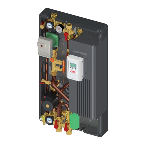
Page 4: Componenti Principali
Installazione, uso e manutenzione SEZIONE 2: DATI TECNICI EXOL AS1 COMPONENTI PRINCIPALI Valvola a sfera DN25 a 3 vie Manometro 0 ÷ 10 bar Maniglia nera con termometro blu Rubinetto di carico-scarico da ½” Valvola di sicurezza 6 bar lato primario (circuito solare) F-F ½” - ¾”... - Page 5 Installazione, uso e manutenzione SEZIONE 2: DATI TECNICI EXOL AS2 COMPONENTI PRINCIPALI Valvola a sfera DN25 a 3 vie Manometro 0 ÷ 10 bar Maniglia nera con termometro blu Rubinetto di carico-scarico da ½” Valvola di sicurezza 6 bar lato primario (circuito solare) F-F ½” - ¾” Circolatore ad alta efficienza Wilo STRATOS PARA 25/1-11 (circuito primario) Valvola di ritegno...
- Page 6 Installazione, uso e manutenzione SEZIONE 2: DATI TECNICI EXOL AR1 COMPONENTI PRINCIPALI Valvola a sfera DN25 a 3 vie Manometro 0 ÷ 10 bar Maniglia nera con termometro blu Rubinetto di carico-scarico da ½” Valvola di sicurezza 6 bar lato primario (circuito solare) F-F ½” - ¾” Circolatore ad alta efficienza Wilo STRATOS PARA 25/1-11 (circuito primario) Valvola di ritegno...
- Page 7 Installazione, uso e manutenzione SEZIONE 2: DATI TECNICI EXOL AR2 COMPONENTI PRINCIPALI Valvola a sfera DN25 a 3 vie Manometro 0 ÷ 10 bar Maniglia nera con termometro blu Rubinetto di carico-scarico da ½” Valvola di sicurezza 6 bar lato primario (circuito solare) F-F ½” - ¾” Circolatore ad alta efficienza Wilo STRATOS PARA 25/1-11 (circuito primario) Valvola di ritegno...
- Page 8 EXOL AS1 / AR1 P1 P3 P2 P1 - P2 = P1 - P3 SCHEMA IDRAULICO EXOL AS2 / AR2 SCHEMA IDRAULICO EXOL AS1 / AR1 1 Valvola a sfera a 3 vie 8 Misuratore di portata VFS 2 Manometro...
- Page 9 Installazione, uso e manutenzione SEZIONE 3: DIMENSIONI E CONNESSIONI EXOL AS1 / AR1 1”F 1”F Mandata primario Ritorno primario (solare) (solare) Mandata secondario Ritorno secondario EXOL AS2 / AR2 1”F 1”F Mandata secondario 1 Ritorno secondario accumulo alto) Mandata secondario 2 (accumulo intermedio) UNITA’...
- Page 10 Installazione, uso e manutenzione SEZIONE 4: ESEMPI DI APPLICAZIONE MINI EXOL AS1 MINI EXOL AS2 Ritorno solare Mandata solare Ritorno solare Mandata solare Uscita ACS Uscita ACS Mandata Mandata secondario secondario accumulo alto Mandata secondario accumulo intermedio Ritorno Ritorno secondario...
-
Page 11: Sezione 5: Installazione
Installazione, uso e manutenzione SEZIONE 5: INSTALLAZIONE CONTROLLI PRELIMINARI Prima di ogni operazione rimuovere con cura l’imballo e controllare la perfetta integrità dell’apparecchiatura. Nel caso si evidenziassero dei difetti o dei danni non installare o cercare di riparare l’apparecchiatura ma rivolgersi al venditore. Smaltire le parti di imballaggio in accordo con leggi e disposizioni vigenti. Il prodotto viene fornito dalla casa produttrice a tenuta. -
Page 12: Sezione 6: Messa In Funzione
Installazione, uso e manutenzione IMPORTANTE! POSIZIONARE IL MODULO IN MANIERA CORRETTA N.B. TASSELLI ESCLUSI DALLA FORNITURA PARTICOLARE SCHIENALE EXOL Successivamente stringere le viti della staffa metallica dalla parte anteriore del modulo, utilizzando gli appositi fori come evidenziato nel particolare in figura 3. SEZIONE 6: MESSA IN FUNZIONE 1 - Assicurarsi la corretta posizione delle valvole di ritegno. - Page 13 Installazione, uso e manutenzione TARATURA DELLA PORTATA TRAMITE IL REGOLATORE DI FLUSSO 10÷40 l/min ATTENZIONE !!! Non tenere premuto per più di 1 minuto TARATURA: - Premere la maniglia-bypass per visualizzare il livello nella scala graduata - Ruotare l’apposito regolatore fino al raggiungimento della portata desiderata - Eseguire la regolazione mantenendo la pressione sulla maniglia-bypass;...
-
Page 14: Sezione 7: Schema Elettrico
Installazione, uso e manutenzione SEZIONE 7: SCHEMA ELETTRICO COLLEGAMENTO ELETTRICO EXOL AS1 / AR1 Bassa tensione max. 12VAC/DC Connessione nella parte sinistra della morsettiera! Linee in tensione 230VAC 50-60Hz Connessione nella parte destra della morsettiera! - Page 15 COLLEGAMENTO ELETTRICO EXOL AS2 / AR2 Bassa tensione max. 12VAC/DC Connessione nella parte sinistra della Linee in tensione 230VAC morsettiera! 50-60Hz Connessione nella parte destra della morsettiera!
- Page 16 Installazione, uso e manutenzione SEZIONE 8: IMPOSTAZIONIE PARAMETRI REGOLATORE DIGITALE LTDC Descrizione menù Descrizione Range impostazioni Default EXOL Impost. Utente 4. IMPOSTAZIONI T min. S1 0°C÷99°C 20°C Priorità accumulo 1 1 / 2 15°C - 7°C ΔT on accumulo 1 - ΔT off accumulo 1 8°C÷50°C 2÷14°C T max.
- Page 17 Installazione, uso e manutenzione Descrizione menù Descrizione Range impostazioni Default EXOL Impost. Utente 7. FUNZIONI SPECIALI 6.4.6 PWM MAX % 50% ÷ 100% 6.4.7 VELOCITA’ QUANDO ON % 10% ÷ 90% Controllo velocità R2 6.5.1 Varianti M1,M2,M3,M4,off 8 sec 6.5.2 Tempo di spurgo 5 sec ÷...
-
Page 18: Sezione 9: Manutenzione
Installazione, uso e manutenzione SCHEMA 27 Collettore solare Accumulo 1 Accumulo 2 Scambiatore Pompa solare Pompa secondario Valvola deviatrice Attenzione: nei moduli mod. AS1 / AR1 non è presente la valvola deviatrice a 3 vie motorizzata. SEZIONE 9: MANUTENZIONE LAVAGGIO DELLO SCAMBIATORE - Intercettare il flusso chiudendo le valvole a sfera rif. - Page 19 Installazione, uso e manutenzione SEZIONE 10: COMPONENTI MISURATORE DI PORTATA / TEMPERATURA VORTEX FLOWSENSOR (VFS) 5 - 100 L/MIN Vortex Flowsensor è un misuratore combinato di portata / temperatura concepito per la produzione di elevati volumi di acqua. E‘ realizzato in acciaio inossidabile, mentre l‘elemento sensibile è a base siliconica realizza- to con tecnologia MEMS.
- Page 20 Lovato S.P.A Indirizzo: Via Selva 4/A, 37040 Gazzolo d’Arcole (VR) Dichiara con la presente che per la quasi-macchina: MODULO DI SEPARAZIONE MINI EXOL AS1-AS2-AR1-AR2, EXOL AS1-AS2-AR1-AR2 • I seguenti requisiti essenziali della Direttiva Macchine (2006/42/CE) sono applicati e rispettati: 1.1,1.1.2,1.1.3,1.1.5,1.1.6,1.2.1,1.2.2,1.2.3,1.2.4,1.2.4.1,1.2.4.2,1.2.4.3,1.2.5, 1.2.6,1.3.1,1.3.2,1.3.3,1.3.4,1.3.6,1.4.1,1.4.2,1.5.1,1.5.5,1.5.6,1.6.1,1.6.5, 1.7.3.
- Page 21 - Washing of heat exchanger SECTION 10: COMPONENTS Picture and technical data are not binding. LOVATO Spa will reserve the right to bring change without obbligation of notice. It is forbidden reproduce copy, drawing or texties, partial or total without previous written authorization.
- Page 22 LOVATO S.p.A. is not responsible for the product modified without permission, and for the replamcements of no-original components. Electrical connection The controller must be installed and connected by authorized staff according to applicable regulations.
- Page 23 Assembling instructions and maintenance SECTION 2: EXOL AS1 TECHNICAL DATA COMPONENTS 3-ways ball valve DN 25 1” F Manometer 0 ÷ 10 bar Black handle with blue thermometer Load/drain tap ½” Solar safety valve 6 bar F-F ½” - ¾”...
- Page 24 Assembling instructions and maintenance SECTION 2: EXOL AS2 TECHNICAL DATA COMPONENTS 3-ways ball valve DN 25 1” F Manometer 0 ÷ 10 bar Black handle with blue thermometer Load/drain tap ½” Solar safety valve 6 bar F-F ½” - ¾” High efficiency circulating pump Wilo STRATOS PARA 25/1-11 (primary circuit) Check valve Flow regulator 10 ÷...
- Page 25 Assembling instructions and maintenance SECTION 2: EXOL AR1 TECHNICAL DATA COMPONENTS 3-ways ball valve DN 25 1” F Manometer 0 ÷ 10 bar Black handle with blue thermometer Load/drain tap ½” Solar safety valve 6 bar F-F ½” - ¾” High efficiency circulating pump Wilo STRATOS PARA 25/1-11 (primary circuit) Check valve Flow regulator 10 ÷...
- Page 26 Assembling instructions and maintenance SECTION 2: EXOL AR2 TECHNICAL DATA COMPONENTS 3-ways ball valve DN 25 1” F Manometer 0 ÷ 10 bar Black handle with blue thermometer Load/drain tap ½” Solar safety valve 6 bar F-F ½” - ¾” High efficiency circulating pump Wilo STRATOS PARA 25/1-11 (primary circuit) Check valve Flow regulator 10 ÷...
- Page 27 EXOL AS1 / AR1 P1 P3 P2 P1 - P2 = P1 - P3 EXOL AS2 / AR2 HYDRAULIC CIRCUIT EXOL AS1 / AR1 HYDRAULIC CIRCUIT 1 3-ways ball valve 8 Vortex flow sensor 2 Manometer 9 High efficiency pump (secondary circuit)
- Page 28 Assembling instructions and maintenance SECTION 3: DIMENSION AND CONNECTION EXOL AS1 / AR1 1”F 1”F Primary supply Primary return (solar) (solar) Secondary circuit Secondary circuit supply return EXOL AS2 / AR2 1”F 1”F Secondary circuit Secondary circuit supply 1 return...
- Page 29 Assembling instructions and maintenance SECTION 4: EXAMPLE OF USE MINI EXOL AS1 MINI EXOL AS2 Primary return Primary supply Primary return Primary supply DHW outlet DHW outlet Secondary Secondary supply 1 supply Secondary supply 2 Secondary Secondary return return DHW storage tank...
-
Page 30: Section 5: Installation
Assembling instructions and maintenance SECTION 5: INSTALLATION PRELIMINARY CHECK Before every operation carefully remove the packaging and verify if there is external damages. In case of damages please do not install the products. Dispose the packaging parts in compliance with the local regulations. The product is supplied by the manufacturer completely screwed. -
Page 31: Section 6: Module Start Up
Assembling instructions and maintenance IMPORTANT! PLACE THE BRACKET IN THE CORRECT PLACE SCREW ANCHORS NOT SUPPLIED EXOL BACK DETAIL Screwing the screws as indicated in the picture 3. SECTION 6: MODULE START UP 1 - Make sure that the check valves are in the correct position. 2 - Close the 3-way ball valve (1) and fill the primary circuit by means of the appropriate fill and drain valves (2) 3 - For the best performance, ensure the system is free from air (vent if necessary). - Page 32 Assembling instructions and maintenance FLOW SETTING BY MEANS OF THE FLOW REGULATOR 10÷40 L/MIN WARNING!!! Do not press for a period longer than 1 minute !!! SETTING: - Push the bypass-handle to show the value on the gauge. - Turn the regulator until the requested flow is reached; - Perform this regulation by keeping the handle pressed;...
-
Page 33: Section 7: Electrical Connection
Assembling instructions and maintenance SECTION 7: ELECTRICAL CONNECTION EXOL AS1 / AR1 ELECTRICAL CONNECTIONS VFS1 Insert in the digital controller Low voltage max. 12VAC/DC Connection on the left part of the terminal Powered lines 230VAC 50-60Hz board! Connection on the right part of the... - Page 34 Assembling instructions and maintenance EXOL AS2 / AR2 ELECTRICAL CONNECTIONS VFS1 Insert in the digital controller Low voltage max. 12VAC/DC Connection on the left part of the terminal board! Powered lines 230VAC 50-60Hz Connection on the right part of the terminal board! S1 Solar sensor S4 Secondary supply sensor...
- Page 35 Assembling instructions and maintenance SECTION 8: ELECTRICAL REGULATOR LTDC INITIAL SETTINGS Menu description Description Settings range Default EXOL User settings 4. SETTINGS T min. S1 0°C÷99°C 20°C Storages priority 1 1 / 2 15°C - 7°C ΔT on storage 1 - ΔT off storage 1 8°C÷50°C 2÷14°C T max.
-
Page 36: Energy Metering
Assembling instructions and maintenance Default EXOL Menu description Description Settings range User settings 6.4.6 PWM MAX % 50% ÷ 100% 6.4.7 Speed when ON % 10% ÷ 90% Speed control R2 6.5.1 Version M1,M2,M3,M4,off 6.5.2 Purging time 5 sec ÷ 600 sec 8 sec 6.5.3 Setting time... -
Page 37: Section 9: Maintenance
Assembling instructions and maintenance SYSTEM 27 Solar collector Storage 1 Storage 2 Heat exchanger Solar pump Secondary circuit pump Diverting valve Warning: AS1 and AR1 modules do not contain powered 3-way diverting valve. SECTION 9: MAINTENANCE WASHING OF HEAT EXCHANGER (PRIMARY CIRCUIT) - Intercept the flow and close the ball valves ref. - Page 38 Assembling instructions and maintenance SECTION 10: COMPONENTS TEMPERATURE/FLOW RATE GAUGE VORTEX FLOWSENSOR (VFS) 5 - 100 l/min Vortex Flowsensor is a combined flow rate/temperature gauge projected for high volume water production. It is made of composite material, while the sensor is made of a silicone base realised with MEMS technology. The gauge is corrosion resistant.
- Page 39 Address: Via Selva 4/A, 37040 Gazzolo d’Arcole (VR) Declares with the present document that the partly completed machinery: SEPARATION MODULE MINI EXOL AS1-AS2-AR1-AR2, EXOL AS1-AS2-AR1-AR2 • The following essential requirement to the Machinery directive(2006/42/CE) are applied and fulfilled:1.1,1.1.2,1.1.3,1.1.5,1.1.6,1.2.1,1.2.2,1.2.3,1.2.4,1.2.4.1, 1.2.4.2,1.2.4.3,1.2.5,1.2.6,1.3.1,1.3.2,1.3.3,1.3.4,1.3.6,1.4.1,1.4.2,1.4.2.1,1.5.1, 1.5.5,1.6.1,1.6.5,1.7.3.
- Page 40 Smart Energy Solutions www.lovatospa.com LOVATO S.p.A. Via Selva, 4/a +39 045 618 2012 mail 37040 Gazzolo d’Arcole info@lovatospa.com lovatospa fax+39 045 618 2017 VERONA - ITALY...
Need help?
Do you have a question about the EXOL AS1 and is the answer not in the manual?
Questions and answers