Table of Contents
Advertisement
Quick Links
Advertisement
Table of Contents

Subscribe to Our Youtube Channel
Related Manuals for zebris JMAOptic


Summary of Contents for zebris JMAOptic
- Page 1 Optic User Manual and technical data...
- Page 2 Hardware User Manual Optic © 2021 zebris Medical GmbH All rights reserved. Reproduction in whole or in part only with the permission of zebris Medical GmbH. Textrelease: R2 Date: 07.05.2021 REF: 79011105 Illustrations of this manual may differ. Manufacturer zebris Medical GmbH...
-
Page 3: Table Of Contents
Table of content 1 User information 1.1. Configuration of the user manual 1.2. Target group 1.3. Symbols used on products, packaging and user manual 2 Area of use and safety 2.1. Intended use 2.1.1. Use 2.1.2. Data export 2.1.3. Produkt life 2.2. - Page 4 3.7. IR-FS / IR Foot Switch 3.7.1. Technical data 3.7.2. State LED 3.7.3. Changing the battery 4 Accessories and spare parts 4.1. Hardware 4.2. Software 5 Putting the system into operation 5.1. Power supply and charging the batteries 5.2. UK-Sensor OJM-UK1 (Lower Jaw Sensor) 5.3.
- Page 5 9 Safety standards and system classification 9.1. Classificatio pursuant to appendix IX of the directive 93/42/EEC 9.2. Safety of medical electrical devices 9.2.1. Connecting the system to other electrical devices 9.2.2. Environment of the patient 9.2.3. Multiple sockets 9.3. Electromagnetic compatibility guideline JMA-Optic Page 5/47 Seite 5/69...
-
Page 6: User Information
(F1 key). In addition, the documents are available on the enclosed installation media as well as online at https://www.zebris.de/infomenue/downloads/ Please read this instruction carefully before using the product for the first time to avoid operating errors and damage. -
Page 7: Symbols Used On Products, Packaging And User Manual
1.3. Symbols used on products, packaging and instructions for use Warning instructions designate a potential danger to the health and safety of users and/or patients. The instructions explain the type of danger and how it can be avoided. Notices designate a potential danger that can cause damage to the device. The instructions explain the type of danger and how it can be avoided. -
Page 8: Area Of Use And Safety
2 Area of use and safety 2.1. Intended use The JMA-Optic system captures the individual mandibular movements of the patient by optical triangulation. From the movement data, parameters are calculated and visualized, which serve to assist in the design of functional dentures and bite splints. The JMA-Optic systems also is able to calculate functional parameters for the programming of virtual and mechanical articulators and export of data for further processing with CAD/CAM or CBCT systems. -
Page 9: Safety
2.2. Safety 2.2.1. Environmental conditions The JMA-Optic is suitable for use in dry interior rooms, as can be found in clinics, medical practices and laboratories. Temperature: 0°C to +45°C Air pressure: 700 - 1100 hPa Relative humidity: max. 85%, non condensing The devices may not be operated in wet zones, damp areas, climatic chambers, under-pressure-, overpressure-, or height-chambers. -
Page 10: Obligations Of User
2.2.3. Obligations of the user It is the obligation of the user: The general guidelines and/or national legislation, national regulations and technical ■ regulations pertaining to medical products are to be applied and fulfilled both during installation and operation of the product appropriate to the stated intended use. To comply with all the safety instructions stated in the operating instructions. -
Page 11: General Safety Information
Patients and measurement data may only be copied, moved or deleted with the help of the ■ database function that is provided by the zebris software application. In the case of the deliberate changing of data without the database function, the user alone bears the full risk. -
Page 12: Safety Information On Heart Pacemakers/Defibrillators
Changing or modifying the measurement system or its accessory parts without the written ■ permission of zebris Medical GmbH is not allowed. If the device is changed without permission, the operator is obliged to carry out suitable examinations and inspections in order to guarantee the secure use. -
Page 13: Produkt Description
3 Product description 3.1. System components In the basic confi guration, the JMA-Optic system consists of the following components: JMA-Optic face bow (receiver) ■ Lower jaw sensor (transmitter) ■ USB power supply for supplying the inductive charger and/or the face bow ■... -
Page 14: Elements Of The Jma-Optic System
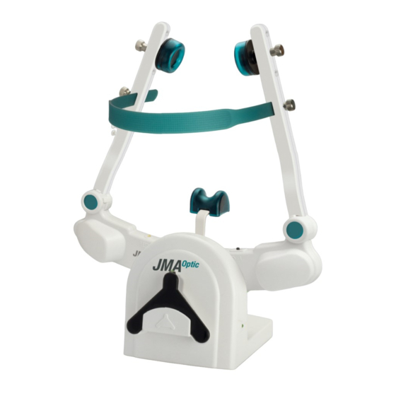
3.3. Elements of the JMA-Optic System IR-Sync LED’s Product label Camera modules left / right Connection socket: external power supply / data transmission Cable guide / strain relief Knurled screw for locking: overhead band Knurled screw for locking: bearing seat Bearing cushions / bearing seat Headband Nose cushion... -
Page 15: Jma-Optic Face Bow
3.4. JMA-Optic Face Bow Cleanliness/integrity of the optical components (1 & 3) must be checked before each use to ensure the accuracy of the measuring system. The transport switch (11) disables the batteries to prevent accidental activation of the head bow and discharge of the batteries. JMA-Optic Page 15/47 Seite 15/69... -
Page 16: Technical Data
3.4.1. Technical data Property Value Dimensions (W x H x L) 222 x 60 x 250 mm Weight 208 g Power supply 5V DC / 2.5W (USB for battery charging) Max. recording rate 60 Hz Measuring accuracy (occlusal) ± 0.05 mm (x, y, z); ROM 15 mm Connector socket device specifi c Push-Pull plug (USB) PC interface... -
Page 17: Stateleds
3.4.3. StateLEDs LED Signal State/Meaning WIFI/(A) Flashing, blue WiFi not connected / active Permanent on, blue WiFi connected and active Recording/(B) Flashing, green Face bow is switched on and ready for operation Permanent on, green Face bow is in operation. Power Supply &... -
Page 18: Sensor Ojm-Uk1 (Lower Jaw Sensor)
3.5. UK-Sensor OJM-UK1 (Lower Jaw Sensor) IR-Sync LED’s Magnetic coupling for lower jaw attachment Product label Status-LED, “Measurement active” (green) Cleanliness/integrity of the optical components (12) must be checked before each use to ensure the accuracy of the measuring system. Deformation/wear of the magnetic coupling balls (13) between the UK sensor and Attachment may reduce the measurement accuracy of the system. -
Page 19: Changing The Battery
3.5.3. Changing the battery To replace the battery of the lower jaw sensor, proceed as follows: Required Materials:Screw driver Type TX 06 ■ Coin Cell Type CR1632 ■ Open the cover of the battery with a screwdriver TX06. Remove the used battery. Insert the new battery (type CR1632) into the battery holder and screw the cover back on. -
Page 20: Induktive Charger Jma-Optic
3.6. Induktive Charger JMA-Optic The inductive charger is used for wireless charging of the JMA-Optic head bow and for storing the head bow and the UK sensor. The charging process starts automatically when the head bow is inserted into the charger and the USB socket (15) is connected to a power source. - Page 21 3.7. IR-FS / IR Foot Switch The foot switch provides wireless control of the WINJAW+ software. Each activation of the foot switch triggers the “next” function in the WINJAW+ software 1x and initiates the next step in the work fl ow. The LED indicates the operation status of the foot switch.
- Page 22 3.7.3. Changing the battery To replace the battery of the foot switch, proceed as follows: Required Materials: Screw driver type PH 0x40 Battery type 6LR91/ 9Volt Open the cover of the battery with a screwdriver PH 0x40. Remove the used battery. Insert the new battery (type 6LR91) into the battery holder and screw the cover back on.
- Page 23 4 Accessories and spare parts The use of consumables beyond the permitted number of applications leads to an increased risk of infection for the patient and possibly to falsi- fi cation of the measurement and analysis results due to changes in the shape of the products, if the sterilization process is used more than once.
- Page 24 Description Figure 01860417 USB Adapter OJM-UA1 connects the JMA-Optic face bow to the PC and charges the battery IR-FS / IR Foot Switch 01860020 for wireless remote control of the system C-Bow JMA-Optic 01970211 for determining a reference plane using the lower jaw sensor 01910025 Pointer Pin 80...
- Page 25 Description Figure 11502508 Overhead Band for JMA-Optic face bow 21030010 WIFI USB Adapter Required for wireless coupling of facebow and PC Knurled Nut, silver 58310141 for JMA-Optic face bow, pack of 2 Knurled Screw, silver 58310121 for JMA-Optic face bow, pack of 2 01960270 Occlusal Attachment for attachment to the anterior teeth...
- Page 26 Description Figure 01560050 Digital Model Transfer - Multisplit Allows the transfer of the jaw position into articulators with the Adesso Multisplit® System. Includes 3x bite fork type SD with bolt thread, bite fork adapter, 1 set of positioning bolts (3 of each type), and 5x positioning foil an a quick guide 01560053 Digital Model Transfer - Splitex...
- Page 27 The basic version contains licences for installation on 3 PC‘s. Extension for installation on an additional computer PC WINJAW+ External Database 07210290 allows installation of zebris database in a freely confi gurable network path 79010230 Hardware User Manual Printing edition is liable to be charged.
- Page 28 5 Putting the system into operation Commissioning the JMA-Optic system requires the USB adapter (REF 01860417), the WiFi USB adapter (REF 21030010) and the WINJAW+ application software. All components are included with the JMA-Optic system. 5.1. Power supply and charging the batteries There are three ways to charge the batteries in the JMA-Optic face bow.
- Page 29 5.2. UK-Sensor OJM-UK1 (Lower Jaw Sensor) Before the lower jaw sensor is set into operation for the fi rst time, the transport lock, which disconnects the battery from the electronics when it is delivered, must be removed. Pull the safety tag in the direction of the arrow away from the housing to activate the battery.
- Page 30 The computer needs to be CE-marked and needs to satisfy the requirements of DIN EN 60950 and/or DIN EN 60601-1. Connecting the JMA-Optic system to a network/data pool can cause unforeseen risks to the patient and third parties. If the database of the WINJAW+ software is installed in a network/data pool, the operator is obliged to ascertain, analyze, evaluate and manage all of the associated risks.
- Page 31 7 Functional checks, preparation, disposal Regular maintenance of the system helps to prevent damage and guarantees its long-term ■ safety. All of the procedures described in these instructions for use concerning maintenance and preparation of the system are to be carried out on a regular basis. If the system or accessory parts show damage, they should be sent to the manufacturer for a ■...
- Page 32 7.2. Checking the measurement function The JMA-Optic system should be periodically checked by the user for proper operation to ensure patient safety on a permanent basis. After hard knocks, or if the face bow or lower jaw sensor has fallen to the floor, a recalibration by the manufacturer must be performed to ensure system high accuracy.
- Page 33 7.3. Troubleshooting In case of problems, please first check the following points: Is the JMA-Optic system switched on and powered? When the green status LED’s on face bow ■ and lower jaw sensor are lit, the batteries are charged or an external power source is connected and the system is ready for use.
- Page 34 7.5. Disposal 7.5.1. Packaging All transport packaging’s delivered by zebris Medical GmbH can be recycled within Germany via the local recycling depots. In order to provide the reuse of the recyclable material contained in the packaging, the zebris Medical GmbH takes part in the dual ZENTEK system that takes over the proper disposal of packaging.
- Page 35 8 Preparation After each use of the JMA-Optic system, reprocessing according to DIN EN ISO 17664 is necessary. All parts with semi-critical contact to the patient must be cleaned, disinfected and sterilized before each use (see: overview table). This applies in particular to the first use after delivery, as these parts are delivered non-sterile.
- Page 36 8.2. Manual cleaning and disinfection The electronic components can be disinfected by wiping and must under no circumstances be immersed in a cleaning solution or cleaned with cleaning liquids or cleaning sprays containing solvents (see: overview table). Wipe disinfection is only permissible when the unit is switched off and the unplugged charging power pack.
- Page 37 Workflow. Manual cleaning Place the components in the cleaning solution for the duration of the specified immersion time, ■ so that the components are sufficiently covered. Ensure that the components do not touch each other and that no air remains in cavities. Support the cleaning process by careful brushing with a soft brush and ultrasonic treatment.
- Page 38 8.3. Mechanical cleaning and disinfection When selecting the washer-disinfector (WD), the following points must be observed: The cleaning and disinfection device must have a fundamentally tested effectiveness ■ (e.g., CE marking in accordance with DIN EN ISO 15883). Basic suitability of the program for instruments as well as sufficient rinsing steps ■...
- Page 39 Mechanical cleaning/disinfection (validated process) Phase Step T[˚C/ ˚F] t[min] Waterquality Comment Pre-rinse < 40/104(cold) Emptying Cleaning 55/131 neodisher® MediClean Dental Emptying Rinse < 40/104 Emptying Rinse < 30/86(cold) VE-W Emptying Thermo- 90/194 VE-W disinfection Emptying Drying > 90/104 T-W: Drinking water VE-W: Fully demineralized water (demineralized, microbiologically at least drinking water quality) Validated with: neodisher®...
- Page 40 8.5. Packaging Place the cleaned and disinfected components in sterile single-use packaging that comply with the following requirements: EN/ISO/ANSI AAMI ISO 11607 (for the USA: FDA approval). ■ Suitable for steam sterilization (temperature resistance to at least 142°C, ■ Sufficiently penetrable by steam). Sufficient protection of the components as well as the sterile packaging against ■...
- Page 41 8.8. Summary table Recommended Product Designation Pretreatment Manual Mechanical Sterilization Multiple use Classification accor- Cleaning/ Cleaning/ ding to RKI/BfArM/ Disinfection Disinfection Kriniko guideline (validated) 01170010 JMA-Optic Face Bow not permissible Immersion permissible not permissible non-critical permissible not permissible Wipe disinfection 01470000 UK-Sensor OJM-UK1 not permissible...
- Page 42 9 Safety standards and system classification 9.1. Classification pursuant to appendix IX of the directive 93/42/EEC The system is classified as a medical product of Class I with a measuring function. 9.2. Safety of medical electrical devices The device fulfills the requirements of the standard DIN EN 60601-1:2013. Classification according to DIN EN 60601-1 Type BF ■...
- Page 43 When operating the JMA-Optic system, the user [2] must be sure never to touch the PC [3] and the patient [1] at the same time. The same applies to all other nonmedical electrical components that are only to be used outside the patient environment. Failure to comply can lead to the occurrence of dangerous leakage currents.
- Page 44 9.3. Electromagnetic compatibility guideline The JMA-Optic system complies with the requirements of the EN 60601-1-2 standard. Detailed information on EMC values and information supplied by the manufacturer can be found in the tables in this section of the user manual. Electrical equipment in the medical field is subject to particular precautionary measures as regards the EMC (Electromagnetic Compatibility) and must be installed and put into operation in accordance with the instructions given below.
- Page 45 Guidelines and manufacturer‘s declaration - Electromagnetic immunity The JMA-Optic is intended for operation in the electromagnetic environment specified below. The customer or the user of the JMA-Optic system should ensure that it is used in such an environment. Immunity IEC 60601- Compliance level Electromagnetic environment - tests...
- Page 46 Guidelines and manufacturer‘s declaration - Electromagnetic immunity The JMA-Optic system is intended for operation in the electromagnetic environment specified below. The customer or the user of the JMA-Optic system should ensure that it is used in such an environment. Immunity IEC 60601- Compliance level Electromagnetic environment -...
- Page 47 Recommended protective distances between portable and mobile RF communications equipment and the JMA-Optic system The JMA-Optic system is intended for operation in an electromagnetic environment in which radiated RF disturbances are controlled. The customer or the user of the JMA-Optic system can help prevent electromagnetic interference by maintaining the minimum separation between portable and mobile RF communication devices (transmitters) and the JMA-Optic system, depending on the output power of the communication device.
Need help?
Do you have a question about the JMAOptic and is the answer not in the manual?
Questions and answers