Table of Contents
Advertisement
Quick Links
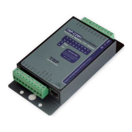
TRP-C24H
16 channels isolated digital output
(Open Collector) Modbus TCP module
.
User's Manual
Printed Sep. 2014 Rev 1.4
Trycom Technology Co., Ltd
No.35, Zhongxing Rd., Guishan Township, Taoyuan County 333, Taiwan.
Tel : 886-3-350-3351 Fax: 886-3-350-3352
Web:
www.trycom.com.tw
Copyright
Copyright Notice: The information in this manual is subject to change without notice to improve reliability, design and
function and
does not represent a commitment on the part manufacturer. No part of this manual may be
reproduced, copied, or transmitted in any form, without prior written permission by the manufacturer. Products
mentioned in this manual are mentioned for identification purposes only. In this manual, product names appearing
may or may not be registered trademarks of their respective companies or copyright.
Advertisement
Table of Contents

Related Manuals for Trycom Technology TRP-C24H

Summary of Contents for Trycom Technology TRP-C24H
- Page 1 TRP-C24H 16 channels isolated digital output (Open Collector) Modbus TCP module User’s Manual Printed Sep. 2014 Rev 1.4 Trycom Technology Co., Ltd No.35, Zhongxing Rd., Guishan Township, Taoyuan County 333, Taiwan. Tel : 886-3-350-3351 Fax: 886-3-350-3352 Web: www.trycom.com.tw Copyright Copyright Notice: The information in this manual is subject to change without notice to improve reliability, design and function and does not represent a commitment on the part manufacturer.
-
Page 2: Specification
When TRP-C24H and TRP-C26H are paired, they can support 16 channels remote control does not require any drivers and software support. The TRP-C24H is also offers the maximum connection 16 host client to link the network server that is easy to operate in Modscan32 ,Modbus Poll,CAS Modbus Scanner and SCADA ...application uses TCP mode and Virtual-COM mode. -
Page 3: Hardware Description
Configuration mode: Trycom Device Manager, WEB settings. Matching remote control: with TRP-C26H. Heart Beat: TCP Port sent string every 5 seconds. TCP Maximum Connection:1~16. Module ID :1~255. Connection type: Screw terminal for maximum AWG 12 wire. ... - Page 4 2-3. Factory Button Hold down the button, and then power on, until the power light flashes, Release the button. 2-4. Factory parameter values...
-
Page 5: Pin Description
2-5. Screw Terminal Pin assignment Description 2-6. Block Diagram 2-7. Pin Description Digital output Channel 5 Digital output Channel F Digital output Channel 4 Digital output Channel E Digital output Channel 3 Digital output Channel D Digital output Channel 2 Digital output Channel C Digital output Channel 1 Digital output Channel B... - Page 6 STEP2: Connect TRP-C24H with netwotk by RJ45 cable. If the cable is properly connected the “LINK” LED will light up. *The TRP-C24H Support Auto-MDIX, A straight-through or crossover RJ45 cable can be used to make a connection directly to the HUB/Router/PC LAN port.
- Page 7 C: Upgrading the TRP-C24H firmware, Refer the Firmware upgrade help file. D: Saving and Loading Configuration from external log File or EEPROM. 4-2. Searching TRP-C24H Once TRP-C24H is connected to the network the DSM software will search it and display it in a window by name, IP address, Mac….Information.
- Page 8 4-3.Configuring Server Properties Select the “NO.” item and Double click to open the module configuration, after setting then click “Submit” will save the configuration to memory.
- Page 9 If DHCP is enabled, the IP address, Subnet mask, Gateway address will be dynamically configuration by DHCP server such router. When DHCP is enabled, but the DHCP server is not available on the network, the TRP-C24H will timeout then back to factory setting IP=192.168.1.1.
- Page 10 Pair Mode: It can be used as a remote manual remote control, when the TRP-C24H 16 DO and TRP-C26H 16 CH DI, TRP-C28H 4 D I/O with TRP-C28H 4 D I / O. Without any driver.
- Page 11 The Web Server can be used to configure the TRP-C24H from any web browser software (such as I.E). In Internet Explorer type the IP Address of the TRP-C24H into the address field and press the Enter key. The following window will appear: Example: If TRP-C24H IP is 192.168.1.1 Please Input the 192.168.1.1 then enters at web address, the web-page will...
- Page 12 4-5 TRPCOM Test Utility The TRPCOM test utility may help to use the debugging program development phase, the user can find this software in our CD internal directory copied to the hard disk, and then directly execute TRPCOM.exe. TRPCOM utility can automatically detect the model, it will list the corresponding function key, It helps developers to understand and control the digital state.
- Page 13 5. TRP-ASCII Communication Protocol TRP-C24H supports three modes of communication Protocol TRP-ASCII, Modbus RTU, Modbus ASCII. TRP-ASCII Command Protocol Description Command Format :”Leading Code”+”ID Address”+”Command”+”CHK”+(cr) . at :”Leading Code”+”ID Address”+”Data”+”CHK”+(cr) . How to calculate the checksum 1. Calculate all characters of the command string to get the ASCII sum, except the character return.
- Page 14 5-1. Setting module configuration Command %IDNNPP00DD(CHK)(cr) First leading code Address of setting module 00-FF(HEX) Syntax New address of setting from 00-FF(HEX) Description The Digital I/O module type define to 40 Data format Checksum (cr) Carriage return Response !ID(CHK) (cr) Command valid ?ID (CHK)(cr) Command Invalid DD: Data Format...
- Page 15 5-2.Digital Output Data Command #IDPPDD(CHK)(cr) First leading code Syntax Address of setting module 00-FF(HEX) description D I/O type :0A/ 00 DO0~DO7 low byte data (Multi-Channel) :0B high byte data D8-D15(Multi-Channel) :1L/ AL: DO0~DO7 low byte data (Single-Channel) L=0~7 :BL : high byte dataD8-D15(Single-Channel) L=0~7 DD:00~FF (Milti-Channel) DD:00 or 01 (Single-Channel) Checksum...
-
Page 16: Read Firmware Version
Address of setting module 00-FF(HEX) description Command for reading module’s version Checksum (cr) Carriage return Response !IDMODDDMMYY(CHK)(cr) MOD :The module’s model DD: Date MM: Month YY : Year ?ID(CHK)(cr) Command Invalid EX: Send command:$01F…Read the TRP-C24H’s version. Response:”!01C24H090113”……. The TRP-C24H’s version date is “01/09/2013”. -
Page 17: Reset Module
(cr) Carriage return Response !IDNNNNNNNNN(CHK)(cr) NNNNNN :The chars from 1~9 chars ?ID(CHK)(cr) Command Invalid EX: Send command:$01M…Read the TRP-C24H’s name. Response:”!01TRPC24H”……. The module’s name is “TRPC24H”. 5-6. Reset Module Command $IDRS(CHK)(cr) First leading code Syntax Address of setting module 00-FF(HEX) - Page 18 Response !ID (CHK)(cr) Command valid ?ID(CHK)(cr) Command Invalid EX: Send Command:”~01O123456789”…Change Name. Response:” !01”……. . Command valid! Send command:$01M…Read the TRP-C24H’s name. Response:”!01123456789”……. The module’s name is “TRPC24H”. 5-8. Set LED operating mode Command ~IDLEDA(CHK)(cr) First leading code Syntax description Address of setting module 00-FF(HEX) Set the module’s LED operating mode...
-
Page 19: Enable Watchdog
5-9 Enable Watchdog Command ~IDWE(CHK)(cr) First leading code Syntax Address of setting module 00-FF(HEX) description Watchdog function Checksum (cr) Carriage return Response !ID(CHK)(cr) Command valid ?ID(CHK)(cr) Command Invalid EX: Send Command:”~01WE”……….Enable Watchdog . .. Response:” !01”……. Command valid. *The user can not change the digital output state when watchdog enable, this mode will keep until the watchdog disable. - Page 20 5-11 Read Watchdog State Command ~IDWR(CHK)(cr) First leading code Syntax Address of setting module 00-FF(HEX) description Read Watchdog State (cr) Carriage return Response !IDWN (CHK)(cr) N=E Enable N=D Disable ?ID(CHK)(cr) Command Invalid EX: Send Command:”~01WR”…Read Watchdog state. Response:” !01WE”……. . Watchdog Enable. 5-12 Read Power on/Safe Mode Command ~ID4V(CHK)(cr)
Need help?
Do you have a question about the TRP-C24H and is the answer not in the manual?
Questions and answers