Table of Contents
Advertisement
Quick Links
Grants Pass, Oregon
- INTRODUCTION -
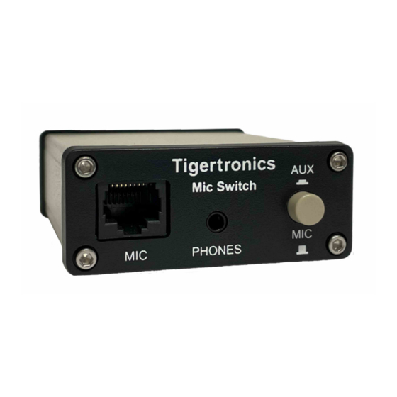
The Tigertronics Microphone Switch Model SW-RJ45
provides a simple yet effective way to connect both a
microphone and a communication device (SignaLink, TNC,
etc.) to your radio's 8-pin Modular RJ-45 Mic jack, and select
between them without needing to disconnect / reconnect the
microphone or cabling.
The switching of all eight lines of the RJ-45 connector is
provided, as well as the switching of stereo audio.
external power is required, and the installation and operation
of the switch is very simple.
As with all of our products, the SW-RJ45 Microphone Switch
is designed and manufactured using only the highest quality
components. Assembly is done using state-of-the-art robotic
production equipment. Strict testing of every unit, and our
high level of quality control insures you of a premium quality
product that will provide many years of dependable service.
- INSTALLATION OVERVIEW -
The SW-RJ45 Microphone Switch is ready to use out of the
box without any configuration needed. However, options
have been provided to allow you to ground the switch
chassis to the radio chassis ground, and to enable RFI
filtering on any of the eight lines going to the radio. These
options are covered in detail in the manual for those wishing
to enable them but they are not necessary for the switch to
function.
As simple as this product is to install and operate, we still
suggest that you spend a little time familiarizing yourself
with it. If after completing the installation you have any
difficulty, please refer to the "Troubleshooting" section at
the end of this manual. It covers most of the common
RJ-45 Microphone Switch
154 Hillview Drive Grants Pass, Oregon 97527
Sales: (541) 474-6700
Installation & Operation
problems that you might run into. Technical Support is also
available if you need it. Please see the "Technical Support"
section of this manual for more information.
The SW-RJ45 Microphone Switch comes supplied with the
cabling that is needed to connect it to your radio. If you are
using this switch with our SignaLink interface, then you
should already have the radio cable (p/n SLCABRJ4) and
audio cable that are needed to attach the SignaLink to the
switch (both of these are supplied with the SignaLink). If
not, then you will need to purchase these separately.
If you are attaching a different product to the switch (TNC,
etc.) then you should already have the interface cable
provided with that device, as well as an audio cable (if
applicable). If not, then you will need to provide and/or
build these cables.
A multi-meter will be needed to verify the location of radio
chassis ground if you want to ground the switch chassis to
the radio chassis ground, or enable RFI filtering.
No
NOTE: If you do not want to ground the switch chassis to
the radio chassis or enable RFI filtering, then you can skip
to "CONNECTING THE SWITCH" at the top of page 3.
Before opening the switch, we suggest that you drain any
static off of your body by momentarily grounding yourself
by touching your radio or computer chassis. To open the
switch case you will need to remove the four front Allen
screws using the supplied Allen wrench. Once the screws
have been removed, gently remove the front cover by
pulling it towards the front of the unit until it pops off. Be
careful not to put pressure on the internal connectors or
switch. Once the front cover has been removed, slide the
circuit board out of the case and set it on a suitable work
surface. An ESD safe work surface is preferred if available.
CAUTION: Care must be taken when grounding the
switch chassis to radio ground. Your equipment could be
damaged if you ground the wrong pin!
1
www.tigertronics.com
- WHAT YOU WILL NEED -
- CONFIGURING THE SWITCH -
Grounding the Switch Chassis
Advertisement
Table of Contents

Related Manuals for Tigertronics SW-RJ45

Summary of Contents for Tigertronics SW-RJ45
- Page 1 Allen wrench. Once the screws have been removed, gently remove the front cover by The SW-RJ45 Microphone Switch is ready to use out of the pulling it towards the front of the unit until it pops off. Be box without any configuration needed.
- Page 2 3 - Set your multi-meter to read resistance and confirm that it is working properly. 4 - Place one multi-meter probe on the radio's exposed (non-painted) metal chassis. The metal around the antenna connector or a non-painting chassis screw is usually a good location for this.
- Page 3 marked “(1)”, “(2)”, “(3)”, etc., and correspond directly to RFI filtering consisting of a ferrite bead and 0.01uf bypass the steps below. cap be enabled for any or all of the eight lines that connect to the radio's mic jack by enabling the jumpers shown in Figure 2 on page 2.
- Page 4 Top View - SWITCH OPERATION- PHONES Operation of the SW-RJ45 Mic Switch is very simple. The front panel “Mic/Aux” switch is used to select the device that you want to use with the radio at any given time. Simply push the switch button IN to select the SignaLink / Aux device.
- Page 5 1PM to 5PM Pacific Time (4PM to 8PM Eastern). Be sure to have your equipment available for testing when you We have made every effort to make the SW-RJ45 Microphone call. Unless you are located over-seas or have extenuating Switch the best product possible. We welcome any comments circumstances, please DO NOT mail, email, or fax your or suggestions that you would like to make.
- Page 6 (not the switch). SignaLinkä trademark Tigertronics Copyright © 2001-2022 Tigertronics - All Rights Reserved (8/22/2022 Rev-A)
Need help?
Do you have a question about the SW-RJ45 and is the answer not in the manual?
Questions and answers