Advertisement
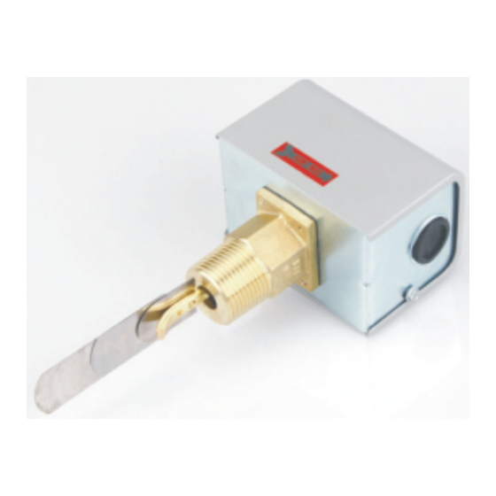
NMR-F61KB Series Liquid Flow Switch
NMR-F61 Liquid Flow Switches are Single - Pole,
Double - Throw (SPDT) flow switches that are used
in liquid lines carrying water,ethylene glycol,or other
liquids not classified as hazardous, They can be
wired to energize one device and de-energize an-
other device powered from the same source when
liquid flow either exceeds or drops below the set
flow rate.
Note: The F61 Flow Switch cannot be used where
the liquid in the pipes will drop below the
liquid's freezing point, causing an internal
freeze-up.
IMPORTANT:
F61 Flow Switches are designed for
use only as operating controls. Where
an operating control failure would re-
sult in personal injury and /or loss of
property, it is the responsibility of the
installer to add devices (safety, limit
controls) or systems (alarm, supervi-
sory systems) that protect against or
warn of control failure.
Use these wrench flats
to tighten the flow switch
at installation.
Paddle
screw
4.00
102 2.00
51
FLOW-MO
1.28
33
1 in. 11-1/2 NPT
Figure 2: F61KB Dimensions (in./mm)
1.39
2.66
68
1.72
4.78
44
121
1.10
28
C
D
1/4
Figure 1: F61KB Flow Switch
2.78
0.875
71
22.23
35
for
1.093
27.76
Ring for
Grounding Screw Hole
Pipe Size
1.00
25
2.00
51
3.00
76
4.00
101
5.00
152
Diameter Hole
0.50
Conduit with
13
Diameter Knockout
0.75
Conduit
19
C
D
1.44
1.00
37
25
2.53
1.13
64
29
3.51
1.13
89
29
6.60
1.13
168
29
6.60
1.13
168
29
Advertisement
Table of Contents

Summary of Contents for Controlium NMR-F61KB Series
- Page 1 NMR-F61KB Series Liquid Flow Switch NMR-F61 Liquid Flow Switches are Single - Pole, Double - Throw (SPDT) flow switches that are used in liquid lines carrying water,ethylene glycol,or other liquids not classified as hazardous, They can be wired to energize one device and de-energize an-...
- Page 2 Installation 1 in 2 in 2.5 in 3 in 4 in 5 in 6 in Original paddle length Figure 3: Trimming Template for the Extra Paddle IMPORTANT: To allwo the switch to detect changes in the flow condition, the paddle must not touch the pipe or any restrictions in Flow the pipe.
- Page 3 Wiring To adjust the setting of the flow switch: WARNING: Shock hazard. 1. Remove the F61 cover. To avoid possible electric shock or dam- 2. For higher flow rates, turn the adjusting screw clock- age to the equipment. disconnect the wise.
- Page 4 Table 1: Typical Flow Rates GPM(m /hr)Required to Actuate Switch Pipe Slze(in.) 1-1/4 1-1/2 2-1/2 65.0 125.0 190.0 375.0 Flow 13.7 18.0 27.5 (14.8) (28.4) (43.1) (85.2) Increase (1.0) (1.3) (1.7) (3.1) (4.1) (6.2) 37.0+ 57.0+ 74.0+ 205.0+ R to Y Minimum Closes** (8.4)
Need help?
Do you have a question about the NMR-F61KB Series and is the answer not in the manual?
Questions and answers