Zehnder Rittling ComfoAir Standard 300 Installer Manual
Hide thumbs
Also See for ComfoAir Standard 300:
- User manual (20 pages) ,
- Installer manual (32 pages) ,
- User manual (20 pages)
Table of Contents
Advertisement
Available languages
Available languages
Advertisement
Chapters
Table of Contents

Subscribe to Our Youtube Channel
Related Manuals for Zehnder Rittling ComfoAir Standard 300


Summary of Contents for Zehnder Rittling ComfoAir Standard 300
- Page 1 ■ Decorative radiators ■ Comfortable indoor ventilation ■ Heating and cooling ceiling systems ■ Clean air solutions ComfoAir Standard 300 ComfoAir Standard 375 Installer manual Manuale installatore Installationsanleitung 1 - EN...
-
Page 2: Table Of Contents
Table of Contents Preface ..................................3 Introduction ................................3 1.1 CE certification and warranty ...........................3 1.1.1 Guarantee conditions ..........................3 1.1.2 Liability ..............................3 1.2 Safety ................................4 1.2.1 Safety regulations..........................4 1.2.2 Safety provisions and measures ......................4 For the Installer ...............................5 2.1 ComfoAir Standard configuration ........................5 2.2 Technical specifications ...........................6 2.3 Dimension sketch ............................8 2.4 Installation conditions ............................8... -
Page 3: Preface
■ Non-compliance with the safety, operating and 1 Introduction maintenance instructions in this manual. The name of the unit is ComfoAir Standard 300/ ■ The use of components not supplied or ComfoAir Standard 375. In this document it will be recommended by the manufacturer. -
Page 4: Safety
■ The ComfoAir Standard is only 1.2 Safety suitable for connection to 230V 50Hz 1.2.1 Safety regulations mains; Always comply with safety regulations ■ It is recommended to take out a in this manual. Non-compliance with maintenance contract so that the the safety regulations, warnings, notes unit is checked on a regular basis. -
Page 5: For The Installer
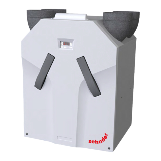
2 For the Installer 2.1 ComfoAir Standard configuration The standard ComfoAir Standard configuration consists of: ■ External casing (A) of coated sheeting; ■ Interior (B) of high-quality, expanded polypropylene (E)PP; ■ 4 connections (C) for the air ducts; ■ 2 plate filters (D) for air purification. Filter classification: ISO Coarse/ ISO ePM1 (ISO 16890 compliant); ■... -
Page 6: Technical Specifications
2.2 Technical specifications ComfoAir Standard 300 ComfoAir Standard 375 ComfoAir Standard 375 ERV Performance (EN 13141-7) Maximum declared airflow (q 300 m 375 m 422 m Thermal Efficiency (humidity) (0,7 x q 74% (60%) Specific fan power 0,20 W/(m³/h) 0,23 W/(m³/h) 0,27 W/(m³/h) - Page 7 Point Instel. cos phi Supply Extract Casing [m³/h] [Pa] dB(A) dB(A) dB(A) 0,15 0,43 0,18 0,44 0,21 0,46 0,33 0,51 0,38 0,41 0,52 0,45 0,52 0,52 0,53 0,65 0,54 0,76 0,54 0,85 0,54 1,22 0,55 1,53 0,55 1,53 0,55 - * Only for the ComfoAir Standard 375 - Sound power reference level is 1pW.
-
Page 8: Dimension Sketch
2.3 Dimension sketch ø160 ø151 CONDENSATION DRAIN CONDENSATION DRAIN RIGHT-HAND VERSION LEFT-HAND VERSION CONDENSATION DRAIN ø32 (OUTSIDE) 2.4 Installation conditions ■ Within a distance of 1 meter or at most the length of the fixed (or supplied) power cable (both 3-core In order to determine whether the ComfoAir Standard and 5-core), an earthed wall outlet must be can be installed in a certain area, the following... -
Page 9: Installation Of The Comfoair Standard
This reduces contact noise as much as possible. The ComfoAir Standard 300 R ComfoAir Standard does not require any space at ComfoAir Standard 300 L PRH the sides for effective operation. ComfoAir Standard 300 R PRH ComfoAir Standard 375 L... -
Page 10: Connection Of The Air Ducts
2.6.2 Connection of the air ducts 2.6.3 Connection of the condensation drain The following aspects must be taken into account, while installing the air ducts: ■ Install the air exhaust duct so it drains in the direction of the ComfoAir Standard. ■... -
Page 11: Commissioning The Comfoair Standard
MENU MENU MENU Enthalpy exchanger select menu MENU MENU When the ComfoAir Standard is fitted with an down enthalpy exchanger the humidity from the extracted supply off supply on air is partly transferred to the fresh supply air. In this (led green) (led green) case you delay the process of drying out the house in... -
Page 12: P Menus For The User
2.7.2 P menus for the user Menu P1 ¨ Status of programmes Status Sub-menu Description Activated Is menu 21 currently active? Yes (1) / No (0) Is menu 22 currently active? Yes (1) / No (0) Is menu 23 currently active? Yes (1) / No (0) Is menu 24 currently active? Yes (1) / No (0) -
Page 13: P Menus For The Installer
2.7.3 P menus for the installer Menus with a line at minimum and maximum value are Reading menus. Menu P3 ¨ Setting ventilation programmes Ventilation programme values Submenu Description Minimum Maximum General Reset 0% or 15% nL / HL 15% / 15% Setting the capacity (in %) of the nL / HL exhaust fan in low position. - Page 14 Menu P5 ¨ Setting additional programmes Additional programme values Submenu Description Minimum Maximum General Reset Activation of the open fire programme. 0 (= No) 1 (= Yes) Confirming the presence of 0 (= No) 1 (= Yes) a Preheater element Only change if a preheater element is installed afterwards or a general reset is given.
- Page 15 Menu P7 ¨ Reading malfunctions (and system information) (Malfunction) information values Submenu Description Minimum Maximum General Reset Current software version. Version number of the software (without “v”) Most recent malfunction. Code in accordance with alarm and malfunction alert Malfunction before the most recent one Code in accordance with alarm and malfunction alert Malfunction before the most recent two Code in accordance with alarm and malfunction alert...
-
Page 16: Programming Air Specifications
2.8 Programming air specifications After installation, the ComfoAir Standard must be programmed. Zehnder ComfoAir Standard 300 and 375 In duct Sound Power Levels (A-weighted) CA Standard 375/300 - Supply 74 dB(A) 73 dB(A) 69 dB(A) 68 dB(A) 64 dB(A) 70 dB(A) -
Page 17: Maintenance By The Installer
(D). " " and " " until “InR” disappears of the 7. Remove the cover panel. display. When reassembling the front cover, the lower 2.9 Maintenance by the installer section must first be inserted behind the raised The following maintenance must be carry out by the edge to ensure a good seal. -
Page 18: Inspecting And Cleaning The Fans
control circuit board panel and fully remove the cables The heat exchanger may contain some residual including the two grommets (K). water! 4. Remove the entire scroll casing by pressing the click fasteners (L). When reassembling the leakage tray the 5. -
Page 19: Malfunctions
5. Remove the base (Q) of the Preheater element. 2.10.1 Malfunction alerts on the digital – The base is fitted in the electronic carriage with operating device four snap connections. Two snap connections In the event of a malfunction, the corresponding are located at the front (visible) and two at the malfunction code will be displayed on the digital back (not visible). -
Page 20: What To Do In The Event Of A Malfunction / Trouble Shooting
2.10.3 What to do in the event of a malfunction / Trouble shooting Below are a number of trouble-shooting tips for the malfunction alerts described previously which can appear on the digital operating device in the event of a malfunction. A1 / A2 / A3 / A4 NTC sensor... - Page 21 A5 / Malfunction in the bypass / preheater element motor Remove the handles from the ComfoAir. Remove the lters from the ComfoAir. Release the front panel by unscrewing the screws. Slide the front panel upwards and remove the front panel from the ComfoAir.
- Page 22 This error will appear when Preheater element after 3 minutes of switching does not heat su ciently. on the preheater element the temperature increase of T1 is less then 4ºC. This can P51 and also happen when there is P57 set to too much cold air passing the the correct value?
- Page 23 Preheater element becomes too hot. º (T1 > 40 Remove the handles from the ComfoAir. Remove the lters from the ComfoAir. Release the front panel by unscrewing the screws. Slide the front panel upwards and remove the front panel from the ComfoAir.
- Page 24 Malfunction Set P60 on "0". Reset the unit (P74 on 1) No communication between the enthalpy sensor and the ComfoAir Is an enthalpy exchanger present? Set P59 to '0' Set P59 to '2' Reset the unit Reset the unit (P74 on 1) (P74 on 1) ,Fil' ,tEr' Internal Filter is dirt y...
- Page 25 E1 / Supply fan / Exhaust fan not rotating Remove the handles from the ComfoAir. Remove the filters from the ComfoAir. Release the front panel by unscrewing the screws. Slide the front panel upwards and remove the front panel from the ComfoAir.
-
Page 26: Malfunctions (Or Problems) Without Alerts
2.10.4 Malfunctions (or problems) without alerts An overview of the malfunctions (or problems) without notifications is given below. Problem/Malfunction Indication Check / action System switched off Power supply on The control circuit board is defective and must be replaced. No power supply Mains power is off. -
Page 27: Service Parts
2.11 Service parts The following table contains an overview of the spare parts available for the ComfoAir Standard. Number Part Fan (left/right) ComfoAir Standard PCB 300 or 375 ComfoSense connection cable Temperature sensor T2 / T4 (in scroll casing of both fans) Temperature sensor T1 / T3 (in top of unit;... -
Page 28: Wiring Diagram: Comfoair Standard - Left-Hand Version
Wiring diagram: ComfoAir STANDARD - LEFT-HAND version 2.12 Wiring diagram: ComfoAir Standard - LEFT-HAND version CASING Blue Brown Brown Blue 1 (RX) 2 (TX) ComfoSense Preheater malfunction indicator of wired 3-position switch White Blue ( - ) Yellow Yellow (0-10V) (0-10V) Blue White... -
Page 29: Wiring Diagram: Comfoair Standard - Right-Hand Version
Wiring diagram: ComfoAir STANDARD - RIGHT-HAND version 2.13 Wiring diagram: ComfoAir Standard - RIGHT-HAND version CASING Blue Brown Brown Blue 1 (RX) 2 (TX) ComfoSense Preheater malfunction indicator of wired 3-position switch White Blue ( - ) Yellow Yellow (0-10V) (0-10V) Blue White... - Page 30 Sommario Premessa ................................31 Introduzione ................................. 31 1.1 Garanzia e responsabilità ..........................31 1.1.1 Condizioni di garanzia.......................... 31 1.1.2 Responsabilità ............................ 31 1.2 Sicurezza ..............................32 1.2.1 Norme di sicurezza..........................32 1.2.2 Misure e disposizioni di sicurezza ......................32 Per l'installatore ..............................33 2.1 ComfoAir Standard configurazione ........................33 2.2 Dati tecnici ..............................34 2.3 Disegno quotato ............................36 2.4 Condizioni di installazione ..........................
-
Page 31: Premessa
I ricambi sono coperti dalla garanzia solo se forniti esiste la possibilità che il ComfoAir Standard 300/ dal costruttore e se sono stati installati da personale ComfoAir Standard 375 sia leggermente diverso autorizzato. -
Page 32: Sicurezza
1.2 Sicurezza ■ Il ComfoAir Standard non è idoneo per essere allacciato alle reti trifase; 1.2.1 Norme di sicurezza ■ Si raccomanda la sottoscrizione di un Rispettare sempre le norme di sicurezza contratto di manutenzione, in modo contenute in questo manuale. Se le che l’unità... -
Page 33: Per L'installatore
2 Per l'installatore 2.1 ComfoAir Standard configurazione Il ComfoAir Standard è composto normalmente da: ■ Involucro esterno rivestito (A); ■ Interno (B) in polipropilene espanso di alta qualità (E)PP; ■ 4 allacciamenti (C) per i condotti dell'aria; ■ 2 filtri (D) per la depurazione dell’aria. Categoria filtro: ISO Coarse/ ePM1 (In conformità con ISO 16890); ■... -
Page 34: Dati Tecnici
2.2 Dati tecnici ComfoAir Standard 300 ComfoAir Standard 375 ComfoAir Standard 375 ERV Prestazionie (EN 13141-7) Flusso d'aria massimo (q 300 m 375 m 422 m Efficienza termica (humidity) (0,7 x q 74% (60%) Consumo elettrico specifico ventilatori 0,20 W/(m³/h) 0,23 W/(m³/h) - Page 35 Punto Funzionam. cos phi Immissione Estrazione Telaio [m³/h] [Pa] dB(A) dB(A) dB(A) 0,15 0,43 0,18 0,44 0,21 0,46 0,33 0,51 0,38 0,41 0,52 0,45 0,52 0,52 0,53 0,65 0,54 0,76 0,54 0,85 0,54 1,22 0,55 1,53 0,55 1,53 0,55 - * Solo per ComfoAir Standard 375. - Il livello di riferimento della potenza sonora è...
-
Page 36: Disegno Quotato
2.3 Disegno quotato ø160 ø151 Spina SCARICO CONDENSA SCARICO CONDENSA DESTRO SINISTRO SCARICO CONDENSA ø32 IT - 36... -
Page 37: Condizioni Di Installazione
ComfoAir ComfoAir Standard 300 L Standard. ComfoAir Standard 300 R ComfoAir Standard 300 L PRH ■ Nell’ambiente scelto per l’installazione devono ComfoAir Standard 300 R PRH essere presenti le seguenti strutture: ComfoAir Standard 375 L - Allacciamenti del condotto dell’aria. -
Page 38: Montaggio Del Comfoair Standard
2.6 Montaggio del ComfoAir Standard Nell’installazione dei condotti dell’aria, sarà necessario rispettate le seguenti norme: ■ Installare il condotto di scarico dell’aria in modo 2.6.1 Montaggio a parete che scarichi verso il ComfoAir Standard. ■ Isolare il condotto di immissione dell’aria esterna e quello di scarico tra il punto di immissione nella parete/soffitto e il ComfoAir Standard. -
Page 39: Allacciamento Dello Scarico Condensa
2.6.3 Allacciamento dello scarico condensa L'allacciamento per lo scarico condensa ha un diametro esterno di 32 mm. E si trova sotto il ComfoAir Standard. ■ Collegare lo scarico condensa per mezzo di una conduttura o di un tubo (sifonato) alla rete di scarico fognario della casa. -
Page 40: Display Sull'unità
Accesso ai menu Menu Possibilità Sequenza Premere Display Descrizione Impostazione degli ingressi RF e tasto ingresso analogico (0-10V) MENU Ritardi Lettura degli stati (dal menu P5) s + ▼ Premere i pulsanti contemporaneamente (3 secondi) L'utente può accedere ai menu P - P1, P2 e P9 - Temperature principalmente per verificare gli stati e impostare i Regolazioni... -
Page 41: Menu P Per L'utente
2.7.2 Menu P per l’utente Menu P1 ¨ Stato delle regolazioni Stato Sottomenu Descrizione Attivato Menu 21 attivo in questo momento? Sì (1) / No (0) Menu 22 attivo in questo momento? Sì (1) / No (0) Menu 23 attivo in questo momento? Sì... -
Page 42: Menu P Per L'installatore
2.7.3 Menu P per l’installatore Menu con indicazioni di valori minimi e massimi impostabili. Menu P3 ¨ Impostazione delle regolazioni di ventilazione Valori delle regolazioni di ventilazione Sottomenu Descrizione Minimo Massimo Reset N.D. 0% o 15% nL / HL 15% / 15% Impostare la potenza (in %) del ventilatore di nL / HL scarico in... - Page 43 Valori regolazioni aggiuntive Sottomenu Descrizione Minimo Massimo Reset Impostazione del volume d'aria necessario per l'abitazione. ■ nL: "volume d'aria normale". ■ HL: "volume d'aria elevato". Nota: L'impostazione del volume d'aria è il punto di partenza per la regolazione delle specifiche di circolazione e quindi l'impostazione dei ventilatori.
- Page 44 Menu P7 ¨ Lettura dei guasti (e delle informazioni di sistema) Valori informazioni (di errore) Sottomenu Descrizione Minimo Massimo Reset Versione del software. Numero della versione del software (senza “v”) Ultimo guasto. Codice secondo l’allarme e indicazione del guasto Penultimo guasto Codice secondo l’allarme e indicazione del guasto Terzultimo guasto.
-
Page 45: Regolazione Delle Specifiche Di Ventilazione
2.8 Regolazione delle specifiche di ventilazione Dopo l'installazione il ComfoAir Standard deve essere regolato. Zehnder ComfoAir Standard 300 and 375 In duct Sound Power Levels (A-weighted) CA Standard 375/300 - Supply 74 dB(A) 73 dB(A) 69 dB(A) 68 dB(A) 64 dB(A) -
Page 46: Manutenzione Per L'installatore
Per impostare i ventilatori, utilizzare il grafico con le specifiche di circolazione del ComfoAir Standard. 9 Qualora i volumi d'aria ora impostati dovessero deviare ancora troppo: Regolare le valvole di conseguenza. 10 Controllare nuovamente tutta l’installazione una volta terminate le operazioni di regolazione. 11 Commutare il ComfoAir Standard (nuovamente) nella posizione di ventilazione 2. -
Page 47: Ispezione Dei Ventilatori
Avvitare le viti con un momento di avvitamento massimo di 1,5 Nm. Equivalente all’incirca alla posizione 2 di un normale trapano avvitatore a batteria. 2.9.2 Ispezione dei ventilatori Controllare i ventilatori 1 volta ogni due anni. 1 Rimuovere lo scambiatore di calore come spiegato nel capitolo sulla manutenzione dello 9 Rimuovere lo scambiatore di calore e la vaschetta scambiatore di calore. -
Page 48: Pulizia Filtro In Presenza Di Un Dispositivo Antigelo
2.9.3 Pulizia filtro in presenza di un dispositivo Codice Descrizione antigelo Sensore NTC Tge guasto. (= Temperatura Scambiatore a terreno) Sensore NTC T1 guasto. Il filtro del dispositivo antigelo (se presente) deve (= Temperatura aria esterna) essere pulito 1 volta ogni 4 anni. Sensore NTC T2 guasto. -
Page 49: Cosa Fare In Caso Di Guasto / Guida Alla Risoluzione Dei Guasti
2.10.3 Cosa fare in caso di guasto / Guida alla risoluzione dei guasti Di seguito vengono fornite indicazioni relative ai messaggi di errore che possono essere visualizzati sul display digitale in caso di guasti. A5 / Guasto al motore del bypass / preriscaldatore. - Page 50 A1 / A2 / A3 / A4 Il sensore NTC T1 / T2 / T3 / T4 è guasto. La temperatura era inferiore a -27ºC Sì o superiore a 127ºC? Tabella della resistenza per i sensori di Ripristinare l'unità Sostituire il (P74 su 1) sensore NTC.
- Page 51 Questo messaggio di errore Preriscaldatore non appare se la temperatura di riscalda a sufficienza. T1 aumenta di meno di 4°C tre minuti dopo l’accensione del preriscaldatore. È P51 e P57 anche possibile che nel sono impostati preriscaldatore scorra troppa sul valore corretto? aria fredda.
- Page 52 Il preriscaldatore si surriscalda. (T1 > 40ºC) Rimuovere le maniglie dal ComfoAir. Rimuovere i filtri dal ComfoAir. Rimuovere i filtri dal ComfoAir. Far scorrere il pannello anteriore verso l'alto e rimuoverlo dal ComfoAir. Allentare il coperchio sigillato r imuovendo le viti. Allentare il coperchio Tensione elettrica sigillato rimuovendo le viti.
- Page 53 Guasto Impostare P60 su "0" Ripristinare l'unità (P74 su 1) EA2 Assenza di comunicazione tra il sensore di entalpia e il ComfoAir. È uno scambiatore entalpico a disposizione? Impostare P59 su "0" Impostare P59 su "2" Ripristinare l'unità Ripristinare l'unità (P74 su 1) (P74 au 1) ,Fil',tEr' Il filtro...
- Page 54 E1 / Il ventilatore di immissione / scarico non gira Rimuovere le maniglie dal ComfoAir. Rimuovere i filtri dal ComfoAir. Allentare il pannello anteriore rimuovendo le viti. Far scorrere il pannello anteriore verso l'alto e rimuoverlo dal ComfoAir. Allentare il coperchio sigillato rimuovendo le viti.
-
Page 55: Guasti (O Problemi) Senza Messaggio
2.10.4 Guasti (o problemi) senza messaggio Di seguito presentiamo una panoramica dei guasti (o problemi) che non sono accompagnati da messaggi. Problema/Guasto Indicazione Controllo / operazione È tutto spento Alimentazione presente La PCB di controllo è guasta e occorre sostituirla. Assenza di corrente La tensione di rete è... -
Page 56: Parti Di Ricambio
Numero Componente Ventilatori (sinistra e destra) PCB nel ComfoAir Standard 300/375 Cavo di collegamento ComfoSense Sensore di temperatura T2 / T4 (nell'involucro della chiocciola di entrambi i ventilatori) Sensore di temperatura T1 / T3 (in alto sull'apparecchio; vicino al carrello elettronico) -
Page 57: Schema Elettrico: Comfoair Standard - Modello Sinistro
Wiring diagram: ComfoAir STANDARD - LEFT-HAND version 2.12 Schema elettrico: ComfoAir Standard – Modello SINISTRO CASING Blue Brown Brown Blue 1 (RX) 2 (TX) ComfoSense Preheater malfunction indicator of wired 3-position switch White Blue ( - ) Yellow Yellow (0-10V) (0-10V) Blue White... -
Page 58: Schema Elettrico: Comfoair Standard - Modello Destro
Wiring diagram: ComfoAir STANDARD - RIGHT-HAND version 2.13 Schema elettrico: ComfoAir Standard – Modello DESTRO CASING Blue Brown Brown Blue 1 (RX) 2 (TX) ComfoSense Preheater malfunction indicator of wired 3-position switch White Blue ( - ) Yellow Yellow (0-10V) (0-10V) Blue White... - Page 59 Inhaltsverzeichnis Vorwort ..................................60 Einleitung ................................60 1.1 Gewährleistung und Haftung ..........................60 1.1.1 Garantiebestimmungen ........................60 1.1.2 Haftung ..............................60 1.2 Sicherheit ..............................61 1.2.1 Sicherheitsvorschriften ........................61 1.2.2 Sicherheitsvorrichtungen und Massnahmen ..................61 Hinweise für den Installateur ..........................62 2.1 ComfoAir Standard Konfiguration ........................62 2.2 Technische Spezifikationen ..........................63 2.3 Massskizze ..............................65 2.4 Installationsvoraussetzungen ..........................65...
-
Page 60: Vorwort
Der Hersteller haftet für keinerlei Schäden, die auf 1 Einleitung folgende Ursachen zurückzuführen sind: ■ Nichtbeachtung der in dieser Anleitung Das Gerät trägt den Namen ComfoAir Standard 300/ aufgeführten Sicherheits-, Bedienungs- und ComfoAir Standard 375 und wird nachfolgend als Wartungshinweise;... -
Page 61: Sicherheit
1.2 Sicherheit ■ Die in diesem Dokument genannten Spezifikationen dürfen nicht geändert 1.2.1 Sicherheitsvorschriften werden; Beachten Sie jederzeit die ■ Jegliche Modifikation der ComfoAir Sicherheitsvorschriften in dieser Standard ist untersagt; Anleitung. Bei Nichtbeachtung ■ Der ComfoAir Standard eignet der Sicherheitsvorschriften sich nicht zum Anschluss an das und Anweisungen sowie der Drehstromnetz;... -
Page 62: Hinweise Für Den Installateur
2 Hinweise für den Installateur 2.1 ComfoAir Standard Konfiguration Der ComfoAir Standard besteht serienmässig aus den folgenden Bauteilen: • Aussengehäuse (A) aus beschichtetem Stahlblech; • Innenraum (B) aus hochwertigem expandierten Polypropylen (E)PP; • 4 Anschlüsse (C) für die Luftkanäle; • 2 Filtertücher (D) für die Luftfilterung. Filterklasse: ISO Coarse und ISO ePM1 gemäß ISO 16890; •... -
Page 63: Technische Spezifikationen
2.2 Technische Spezifikationen ComfoAir Standard 300 ComfoAir Standard 375 ComfoAir Standard 375 ERV Leistung (EN 13141-7) Maximaler deklarierter Luftmenge 300 m 375 m 422 m Thermischer Wirkungsgrad 74% (60%) (Luftfeuchtigkeit) (0,7 x q Spezifische Lüfterleistung 0,20 W/(m³/h) 0,23 W/(m³/h) 0,27 W/(m³/h) - Page 64 Punkt Einstel. cos phi Supply Extract Gehäuse [m³/h] [Pa] dB(A) dB(A) dB(A) 0,15 0,43 0,18 0,44 0,21 0,46 0,33 0,51 0,38 0,41 0,52 0,45 0,52 0,52 0,53 0,65 0,54 0,76 0,54 0,85 0,54 1,22 0,55 1,53 0,55 1,53 0,55 - * Nur für den ComfoAir Standard 375. - Der Referenzwert für die Schallleistung beträgt 1 pW.
-
Page 65: Massskizze
2.3 Massskizze ø160 ø151 KONDENSATABLAUF KONDENSATABLAUF RECHTE AUSFÜHRUNG LINKE AUSFÜHRUNG KONDENSATABLAUF ø32 2.4 Installationsvoraussetzungen ■ Im Raum müssen die folgenden Vorrichtungen vorhanden sein: Um beurteilen zu können, ob die Installation des - Luftkanalanschlüsse. ComfoAir Standard in einem bestimmten Raum - 230 V Netzanschluss. möglich ist, sind folgende Punkte zu beachten: - Anschluss für den Kondensatablauf. -
Page 66: Installation Des Comfoair Standard
Freiraum. ComfoAir Standard 300 L ComfoAir Standard 300 R Montieren Sie den ComfoAir Standard auf Grund ComfoAir Standard 300 L PRH von möglichen Kontaktgeräuschen nicht mit der ComfoAir Standard 300 R PRH Seite an eine Wand. ComfoAir Standard 375 L ComfoAir Standard 375 R 1. -
Page 67: Anschluss Der Luftkanäle
2.6.2 Anschluss der Luftkanäle 2.6.3 Anschluss des Kondensatablaufs Bei der Installation der Luftkanäle sind die folgenden Regeln zu beachten: ■ Der Abluftkanal muss ein Gefälle zum ComfoAir Standard aufweisen. ■ Isolieren Sie den Außenluftzufuhrkanal und den Abluftkanal zwischen der Dach-/ ComfoAir Standard - LINKS Giebeldurchführung und dem ComfoAir Standard dampfdicht. -
Page 68: Inbetriebnahme Des Comfoair Standard
2.7.1 Display am Gerät Sorgen Sie dafür, dass das Schlauchende Der ComfoAir Standard kann mit einem Display mindestens 60 mm unter dem Wasserspiegel in Betrieb genommen und bedient werden. Bei ausmündet. Auf diese Weise kann der ComfoAir dem Display handelt es sich um ein am ComfoAir Standard keine Luft ansaugen. -
Page 69: P-Menüs Für Den Benutzer
Einige P-Menüs (z. B. P1 und P9) können nur Die Anzeige kann nicht verwendet werden für die gelesen werden. Festsetzung der Belüftungsstufen der ComfoAir Ende (Lesen) Menü Standard. Die Pfeiltasten sind nur für die Festsetzung der zusätzlichen Programme. ■ Drücken Sie auf “MENU” (anstelle von “OK”). 2.7.2 P-Menüs für den Benutzer Menü... -
Page 70: P-Menüs Für Den Installateur
Menü P9 ¨ Status der Regelungen (aus Menü P5 Zusatzregelungen) Status Submenü Bezeichnung Aktiviert Kaminregelung aktiv? Ja (1) / Nein (0) Bypass offen (=ja) / geschlossen (=nein)? Ja (1) / Nein (0) Analogeingang (0-10V) aktiv? Ja (1) / Nein (0) Frostschutz aktiv? Ja (1) / Nein (0) Enthalpietauscher aktiv? - Page 71 Menü P5 ¨ Einstellung von Zusatzregelungen Werte Zusatzregelungen Submenü Bezeichnung Minimum Maximum Vollständiger Reset Aktivierung der 0 (= Nein) 1 (= Ja) Kaminregelung. Vorhandensein eines 0 (= Nein) 1 (= Ja) Frostschutzelements angeben. Hinweis: Änderungen nur nach einem vollständigen Reset oder wenn nachträglich ein Vorwärmer installiert wurde vornehmen. Einstellung der Frostschutzregelung: ■...
- Page 72 Menü P6 ¨ Einstellung von Zusatzregelungen Werte Zusatzregelungen Submenü Bezeichnung Minimum Maximum Vollständiger Reset Vorhandensein eines Bodentauschers angeben. 0 (= Nein) 3 (= Ja) ■ 0; kein Bodentauscher vorhanden ■ 1; Bodentauscher vorhanden ■ 3; Bodentauscher ungesteuert vorhanden Nur ein ungesteuert Bodemtauscher kann werden eingesetzt. Menü...
-
Page 73: Einstellung Der Luftspezifikationen
2.8 Einstellung der Luftspezifikationen Der ComfoAir Standard muss nach der Installation eingestellt werden. Zehnder ComfoAir Standard 300 and 375 In duct Sound Power Levels (A-weighted) CA Standard 375/300 - Supply 74 dB(A) 73 dB(A) 69 dB(A) 68 dB(A) 64 dB(A) -
Page 74: Pflege Durch Den Installateur
Verwenden Sie zur Einstellung der Ventilatoren das Diagramm mit den Luftspezifikationen des ComfoAir Standard. 9. Sollten die bisher eingestellten Luftmengen noch zu viel abweichen: Stellen Sie die Ventile dann nach. 10. Kontrollieren Sie nach der Einstellung aller Ventilstufen noch einmal die gesamte Anlage. 11. -
Page 75: Inspektion Der Ventilatoren
Ziehen Sie die Schrauben mit einem maximalen Überprüfen Sie beim Montieren des Drehmoment von 1,5 Nm an. Dies entspricht Ablaufblechs, ob die Löcher im Ablaufblech sich ungefähr der Stufe 2 eines gängigen an der Seite des Kondensatablaufs befinden. Schraubbohrers. 2.9.2 Inspektion der Ventilatoren Kontrollieren Sie die Ventilatoren alle 2 Jahre. -
Page 76: Filterreinigung Bei Geräten Mit Frostschutzelement
2.9.3 Filterreinigung bei Geräten mit 2.10.1 Störungsmeldungen auf dem digitalen Frostschutzelement Bediengerät Bei einer Störung erscheint auf dem digitalen Das Filter des Frostschutzelements muss (wenn Bediengerät eine entsprechende Störungsmeldung. vorhanden), alle 4 Jahre gereinigt werden. Im Folgenden finden Sie eine Übersicht der Störungsmelder, die auf dem Bildschirm des digitalen 1. -
Page 77: Was Im Falle Einer Störung Zu Tun? / Störungsübersicht
2.10.3 Was im Falle einer Störung zu tun? / Störungsübersicht Im Folgenden geben wir Ihnen Hinweise für das Vorgehen bei den genannten Störungsmeldungen, die auf dem digitalen Gerät angezeigt werden. A1 / A2 / A3 / A4 NTC-Fühler T1 / T2 / T3 / T4 ist defekt. - Page 78 A5 / Störung am Motor von Bypass oder Vorwämer. Handgriffe aus dem ComfoAir ziehen. Filter aus dem ComfoAir ziehen. Lösen Sie die Front- platte, indem Sie die Schrauben entfernen. Schieben Sie die Front- platte hoch und nehmen Sie die Frontplatte des ComfoAir ab.
- Page 79 Diese Fehlermeldung Vorwärmer erhitzt nicht wird angezeigt, wenn die ausreichend. Temperatur von T1 drei Minuten nach Einschalten des Vorwärmers um weniger als 4 P51 und P57 °C gestiegen ist. Es ist auch auf korrekten Nein möglich, dass zu viel kalte Wert eingestellt? Luft am Spannungsversorgung...
- Page 80 Vorwärmer zu heiß. (T1 > 40 ºC) Handgriffe aus dem ComfoAir ziehen. Filter aus dem ComfoAir ziehen. Lösen Sie die Frontplatte, indem Sie die Schrauben entfernen. Schieben Sie die Frontplatte hoch und nehmen Sie die Front- platte des ComfoAir ab. Lösen Sie die Dichtungs- platte, indem Sie die Schrauben entfernen.
- Page 81 Störung P60 auf „0“ stellen. Gerät zurücksetzen (P74 auf 1) Keine Kommunikation zwischen Enthalpiesensor und ComfoAir. Ist ein Nein Enthalpietauscher vorhanden? P59 auf "0" stellen P59 auf "2" stellen Gerät zurücksetzen Gerät zurücksetzen (P74 auf 1) (P74 auf 1) ,Fil',tEr' Internes Filter verschmutzt Maximal 4 Sekunden auf OK auf dem Bildschirm...
- Page 82 E1 / Zu-/Abluftventilator läuft nicht. Handgriffe aus dem ComfoAir ziehen. Filter aus dem ComfoAir ziehen. Lösen Sie die Front- platte, indem Sie die Schrauben entfernen. Schieben Sie die Front- platte hoch und nehmen Sie die Frontplatte des ComfoAir ab. Lösen Sie die Dichtungs- platte, indem Sie die Schrauben entfernen.
-
Page 83: Störungen (Oder Probleme) Ohne Meldung
2.10.4 Störungen (oder Probleme) ohne Meldung Im Folgenden eine Übersicht über Störungen (oder Probleme), bei denen keine Meldung erscheint. Problem / Störung Ursache/Anzeichen Kontrolle / Maßnahme Alles aus Speisespannung Die Steurerplatine ist defekt und muss ersetzt werden. Keine Speisespannung Netzspannung ist ausgefallen. Hohe Einblastemperatur Bypass bleibt geschlossen Senken Sie die Komforttemperatur. -
Page 84: Ersatzteile
Im Folgenden eine Übersicht der verfügbaren Ersatzteile für den ComfoAir. Nummer Teil Ventilatoren (links und rechts) Steuerplatine in ComfoAir Standard 300/375 ComfoSense Verbindungskabel Temperaturfühler T2 / T4 (in Schneckenhaus der beiden Ventilatoren) Temperaturfühler T1 /T3 (oben im Gerät, bei Elektronikschlitten) Servomotor &... -
Page 85: Schaltplan: Comfoair Standard - Linksseitige Ausführung
Wiring diagram: ComfoAir STANDARD - LEFT-HAND version 2.12 Schaltplan: ComfoAir Standard – LINKSSEITIGE Ausführung CASING Blue Brown Brown Blue 1 (RX) 2 (TX) ComfoSense Preheater malfunction indicator of wired 3-position switch White Blue ( - ) Yellow Yellow (0-10V) (0-10V) Blue White ( - ) -
Page 86: Schaltplan: Comfoair Standard - Rechtsseitige Ausführung
Wiring diagram: ComfoAir STANDARD - RIGHT-HAND version 2.13 Schaltplan: ComfoAir Standard – RECHTSSEITIGE Ausführung CASING Blue Brown Brown Blue 1 (RX) 2 (TX) ComfoSense Preheater malfunction indicator of wired 3-position switch White Blue ( - ) Yellow Yellow (0-10V) (0-10V) Blue White ( - ) - Page 87 87 - DE...
- Page 88 Zehnder Group Sales International Almweg 34 • 77933 Lahr • Germany T +49 78 21 586-392 • F +49 78 21 586-406 sales.international@zehndergroup.com • www.international.zehnder-systems.com Zehnder Group Italia S.r.l. Via XXV Luglio 6 • 41011 Campogalliano MO • Italy T +39 059 978 62 00 · F +39 059 978 62 01 info@zehnder.it •...
Need help?
Do you have a question about the ComfoAir Standard 300 and is the answer not in the manual?
Questions and answers