Table of Contents
Advertisement
Available languages
Available languages
Quick Links
L2121
Rev. A
INDEX:
English
............ Instruction Sheet .....................page ..................1-6
Français
........... Notice d'Emploi .......................page ..............10-13
Deutsch
........... Bedienungsanleitung...............Seite ..............14-17
Italiano
............ Manuale di istruzioni ..............pagina............18-21
Español
........... Instrucciones ...........................página............22-25
Nederlands
3/99
AHP-15T
(10500)
.... Handleiding .............................bladzidje ........26-29
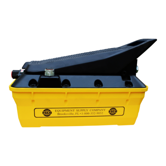
Instruction Sheet
AHP-15T (10500), AHP-25TP(10502),
AHP-35T (10504)
Air Hydraulic Pumps
AHP-25TP
(10502)
AHP-35T
(10504)
1
Advertisement
Table of Contents

Related Manuals for Esco AHP-15T


Summary of Contents for Esco AHP-15T
- Page 1 Instruction Sheet AHP-15T (10500), AHP-25TP(10502), AHP-35T (10504) Air Hydraulic Pumps L2121 Rev. A 3/99 AHP-15T AHP-25TP (10500) (10502) AHP-35T (10504) INDEX: English .... Instruction Sheet .....page ....1-6 Français ... Notice d’Emploi .......page ....10-13 Deutsch ... Bedienungsanleitung....Seite ....14-17 Italiano .... Manuale di istruzioni ....pagina....18-21 Español...
- Page 2 Instruction Sheet AHP-15T (10500), AHP-25TP(10502), AHP-35T (10504) Air Hydraulic Pumps 1.0 IMPORTANT RECEIVING INSTRUCTIONS Visually inspect all components for shipping damage. If shipping damage is found, notify carrier at once. Shipping damage is not covered by warranty. The carrier is responsible for all repair and replacement costs resulting from damage in shipment.
- Page 3 to ensure that pieces of tape do not break off and enter the system. See illustration 2. Thread hose into outlet port of pump (A). Torque hose fittings to 65 - 75 ft-lbs. [88 - 102 Nm]. The outlet port is located on the opposite end of pump from the air inlet connection.
- Page 4 4.5 MOUNTING PUMP. The 7004 pump can be 9.05" [230mm] mounted horizontally or vertically. If mounted vertically, position pump with hydraulic outlet port facing down. a) The four holes in the bottom of the reservoir should be used for bolting through the mounting surface into the reservoir (see illustration 5).
-
Page 5: Operation
5.0 OPERATION RELEASE PRESSURE 5.1 OIL LEVEL. Check the oil level of pump and add oil if necessary (See Installation section, step 4.6). 5.2 VENTING PUMP. Make sure the pump reservoir is vented (See Installation section, step 4.4). 5.3 TREADLE OPERATION. See illustration 8. a ) T O A D V A N C E C Y L I N D E R . -
Page 6: Cleaning The Air Inlet Filter
DO NOT disassemble the pump. For repair service, contact the Authorized Service Center in your area. If you do not know the name of your local service center, contact ESCO at 1-800-352-9852 or 352-754-4508 for a list of Authorized Service Centers PROBLEM... - Page 8 Illustrations Closed Vented Fermé Aéré Geschlossen Entlüftet Chiuso Ventilazione Cerrado Abierto Gesloten Ontlucht 9.05" [230mm]...
- Page 9 RELEASE PRESSURE 7.50 [190,5] 6.38 1.65 [162,1] [41,9] 9.68 [245,9] 12.73 [323,3] 13.71 [348,3]...
-
Page 10: Caractéristiques
à fonctionnement avec support utilisable hydraulique d’air 700 bar (70 psi) (10.000 psi) AHP-15T .375-18 3,0 SCMM 2,8-10,3 bar 2,5 l (153 in 0,1 l/min 79 dBA 6,4 kg (14 lbs.) (10500) NPTF (10 SCFM) (40-150 psi) -
Page 11: Raccordements Hydrauliques
4.3 RACCORDEMENTS HYDRAULIQUES ATTENTION Le réservoir de la pompe doit être aéré en utilisant NOTE : Enrober de 1 tour de ruban Téflon les lune des deux options pour éviter les risques de raccords de flexible NPTF uniquement, en ne couvrant cavitation et de dommages à... -
Page 12: Entretien
5.0 FONCTIONNEMENT 5.5 RÉGLAGE DE LA PRESSION. Pour obtenir une pression hydraulique inférieure au maximum, soit 5.1 NIVEAU D’HUILE. Vérifier le niveau d’huile de la installer un clapet de décharge réglable sur le circuit, soit pompe et faire lappoint si nécessaire (voir la section limiter la pression dentrée dair. -
Page 13: Dépannage
7.0 DÉPANNAGE Lentretien et la réparation de la pompe et des composants du système doivent être exclusivement confiés à des techniciens qualifiés en hydraulique. Une panne dans le système nest pas nécessairement due à un mauvais fonctionnement de la pompe. Pour déterminer la cause du problème, inclure le système complet dans toute procédure de diagnostic. - Page 14 4,83 bar bereich Fassungs- geräusch mit Halterung anschlüsse (70 psi) vermögen 700 bar Nutzbar (10,000 psi) AHP-15T .375-18 3,0 SCMM 2,8-10,3 bar 2,5 l (153 in 0,1 l/min 79 dBA 6,4 kg (14 lbs.) 2,1 l (127 in (10500) NPTF...
-
Page 15: Betrieb
4.3 HYDRAULIKANSCHLÜSSE. Entlüftungsverfahren entlüftet werden. Andernfalls kann es bereits nach kurzer Zeit zur Bildung von HINWEIS: Nur für die NPTF-Schlauchanschlüsse 1 Dampfsäcken kommen, die die Pumpe Lagen Teflonband benutzen, wobei der erste volle beschädigen können. Gewindegang frei bleiben muß, um zu verhindern, daß das Band reißt und in das System gelangt. -
Page 16: Wartung
5.3 BEDIENUNG DES FUSSHEBELS: Siehe Abb. 8, f) Um zu prüfen, ob die Pumpe gefüllt ist, normal mit Seite 9. einem angeschlossenen Zylinder arbeiten. Wenn der Zylinder nicht ausfährt, Schritt 5.4 d wiederholen. a) AUSFAHREN DES ZYLINDERS. Das ,,PRESSURE“ (Druck)-Ende des Fußhebels niederdrücken, und die 5.5 DRUCKEINSTELLUNG. -
Page 17: Störungssuche
7.0 STÖRUNGSSUCHE S e r v i c ea r be it en de r P um pe od er Systemkomponenten dürfen nur von qualifizierten Hydrauliktechnikern vorgenommen werden. Ein Systemausfall kann, muß aber nicht durch eine Fehlfunktion der Pumpe verursacht sein. Um die Fehlerquelle festzustellen, muß... -
Page 18: Installazione
4,83 bar pressione utilizzabile 700 bar con base (70 psi) aria (10.000 psi) AHP-15T .375-18 3,0 SCMM 2,8-10,3 bar 2,5 l (153 in 0,1 l/min 79 dBA 6,4 kg (14 lbs.) 2,1 l (127 in (10500) NPTF... -
Page 19: Funzionamento
4.3 COLLEGAMENTI OLEODINAMICI Per utilizzarlo come bocca di ritorno al serbatoio, rimuovere il tappo esagonale, collegando nel foro NOTA: solamente per i raccordi NPTF dei tubi flessibili, un’idonea linea di ritorno. Serrare la linea ad una coppia usare nastro di teflon come guarnizione, avvolgendolo di 20-27 N•m (15-20 ft-lbs). -
Page 20: Manutenzione
serbatoio sia ventilato (vedere il punto 4.4). 5.5 REGOLAZIONE DELLA PRESSIONE. Per ottenere nel circuito una pressione oleodinamica inferiore a quella 5.3 IMPIEGO DELLA PEDALIERA Vedere la figura 8, massima, installare una valvola limitatrice di pressione pagina 9. del tipo regolabile o limitare la pressione dell’aria compressa in ingresso. -
Page 21: Ricerca Dei Guasti
7.0 RICERCA DEI GUASTI La manutenzione della pompa o dei componenti del sistema va eseguita esclusivamente da tecnici idraulici specializzati. Un guasto del sistema può dipendere dal malfunzionamento di una pompa. Per determinare l’origine del problema, è necessario includere tutti i componenti del sistema nella procedura di diagnosi. -
Page 22: Especificaciones
70 psi presión de de aceite de aceite funcionamiento utilizable hidráulicas (4,83 bar) aire 10.000 psi (700 bar) AHP-15T .375-18 3,0 SCMM 2,8-10,3 bar 2,5 l (153 in 0,1 l/min 79 dBA 6,4 kg (14 lbs.) (10500) NPTF (10 SCFM) - Page 23 Para usarlo como conexión de retorno al depósito, quite el tapón plano del tapón hexagonal e instale una línea de retorno compatible. Apriete la línea de retorno a 20-27 Nm (15-20 lb-pie) en el tapón hexagonal. 4.3 CONEXIONES HIDRAULICAS ATENCION NOTA: Ponga una vuelta y media de cinta de Teflon en El depósito de la bomba debe ventilarse usando los adaptadores de manguera con roscas NPT...
-
Page 24: Mantenimiento
la bomba y añada si es necesario (vea la sección 5.5 AJUSTE DE PRESION. Para obtener una presión Instalación, paso 4.6). hidráulica inferior a la máxima, instale una válvula de alivio ajustable en el sistema, o limite la presión 5.2 VENTILACION DE LA BOMBA. Asegúrese que el neumática de entrada. -
Page 25: Localizacion De Averias
7.0 LOCALIZACION DE AVERIAS La bomba y los componentes del sistema deben ser reparados solamente por técnicos con experiencia en sistemas hidráulicos. La falla de un sistema puede o no deberse a una avería de la bomba. Para determinar la causa del problema, en cualquier procedimiento de diagnóstico se debe incluir el sistema completo. - Page 26 4,83 bar drukbereik Bruikbarr bij 700 bar tijdens bedrijf met beugel poorten (70 psi) (10.000 psi) AHP-15T .375-18 3,0 SCMM 2,8-10,3 bar 2,5 l (153 in 0,1 l/min 79 dBA 6,4 kg (14 lbs.) (10500) NPTF (10 SCFM)
-
Page 27: Hydraulische Aansluitingen
4.3 HYDRAULISCHE AANSLUITINGEN beschadigen. OPMERKING: Wikkel alleen rond de fittingen van de NPTF slang anderhalve slag Teflon-band en houd de 4.5 MONTAGE VAN POMP. De 7004 pomp kan eerste volledige gang vrij om te voorkomen dat stukjes horizontaal of verticaal worden gemonteerd. Bij verticale band afbreken en in het systeem terecht komen. - Page 28 a) UITLOPEN VAN CILINDER. Druk het "PRESSURE" 5.5 DRUKAFSTELLING. Om minder dan de maximale (druk) einde van het voetpedaal in en de pomp begint hydraulische druk te verkrijgen brengt u ofwel een hydraulische olie naar het systeem te pompen. instelbare ontlastklep in het systeem aan of beperkt u de druk van de inlaatlucht.
-
Page 29: Problemen Oplossen
7.0 PROBLEMEN OPLOSSEN De pomp en de systeemonderdelen mogen uitsluitend d o o r e r k e n d e h y d r a u l i s c h e m o n t e u r s w o r d en onderhouden. - Page 32 EQUIPMENT SUPPLY COMPANY 15424 Flight Path Drive • Brooksville, Florida 34609 Manufacturers of Equipment for Truck, Tractor, and Earth Mover Tire Changing Phone 800/352-9852, 352/754-1117 • Fax 352/754-4508...
Need help?
Do you have a question about the AHP-15T and is the answer not in the manual?
Questions and answers