Table of Contents
Advertisement
Quick Links
Multi-function Drill Control
Electro-Magnetic Compatibility (EMC)
This product complies with Council Directive 2004/108/EC
when installed and used in accordance with the relevant
instructions.
Service and Technical Support
PLEASE CONTACT YOUR NEAREST DISTRIBUTOR
If unknown then fax: 44 (0) 1453 733322
© Copyright RDS Technology Ltd 2006
Our policy is one of continuous improvement and the
information in this document is subject to change without
notice. Check the software reference matches that
displayed by the instrument.
Document number
S/DC/500-10-537 : Issue 1 : 12/1/06
UK537-1.DOC
User Guide
Neumasem Plus
Drill Control
Calibration and Operation
Software Ref: WZ 813-001 rev.01
1
Advertisement
Table of Contents

Summary of Contents for Sola Neumasem Plus
- Page 1 Check the software reference matches that displayed by the instrument. Document number S/DC/500-10-537 : Issue 1 : 12/1/06 UK537-1.DOC User Guide Neumasem Plus Drill Control Calibration and Operation Software Ref: WZ 813-001 rev.01...
-
Page 2: Table Of Contents
Sola Neumasem Plus Drill Control Contents Contents_______________________________________________2 1. Overview ___________________________________________4 Normal Display Mode ___________________________________________________4 Programming Modes____________________________________________________4 2. The Control Switches ________________________________5 3. Forward Speed ______________________________________6 Display Forward Speed____________________________________________________6 Forward Speed Alarm _____________________________________________________6 Disable Forward Speed Alarm ______________________________________________6 Speed Sensor Calibration__________________________________________________7 ‘Autocal’_______________________________________________________________7... - Page 3 Sola Neumasem Plus Drill Control 7. Seed Distribution Shaft Speed ______________________ 20 Display Shaft Speed_____________________________________________________ 20 Distribution Shaft Speed Alarm ___________________________________________ 20 Set Alarm Speed for Distribution Shaft _____________________________________ 20 8. Hopper Level ______________________________________ 22 Enable / Disable Hopper Level Alarm ______________________________________ 22 9.
-
Page 4: Overview
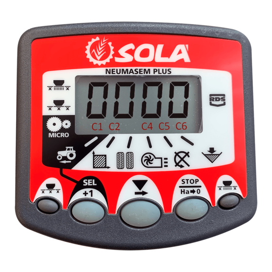
Sola Neumasem Plus Drill Control Overview The Sola Neumasem Drill Control monitors several functions of the seed drill, sets the seeding width, and controls the tramlining function of both conventional and pneumatic type seed drills. The instrument has an illuminated 4-digit display with 6 display functions and alarm functions for forward speed, fan rpm, seed distribution shaft rpm and hopper level. -
Page 5: The Control Switches
Sola Neumasem Plus Drill Control The Control Switches There are five switches on the front panel used individually or in combination to select, programme, or reset a function. Status Indicators Left/Right Shutoff Whole Shutoff Channel Indicators 'Micro' metering calibration set... -
Page 6: Forward Speed
Sola Neumasem Plus Drill Control Forward Speed Display Forward Speed Forward Speed displays for 10 seconds before returning to the tramline display. If an alarm condition occurs, the display will default to the appropriate channel, the buzzer will sound 5... -
Page 7: Speed Sensor Calibration
Sola Neumasem Plus Drill Control Speed Sensor Calibration The forward speed sensor is magnetically operated and senses the seed shaft rotation. In order to display the correct speed and accumulate area correctly, the instrument must be programmed with the correct Speed Sensor Factor (SSF). This is the distance travelled between two signal pulses received from the sensor. - Page 8 Sola Neumasem Plus Drill Control Drive the vehicle until the chosen reference point on the tractor/implement is opposite the second marker. The instrument counts and displays the sensor pulses received over the distance travelled. Press the button to complete the Autocal routine (fig.
-
Page 9: Area Total / Implement Width
Sola Neumasem Plus Drill Control Area Total / Implement Width The area is derived from the forward speed and the programmed implement width and is accumulated to whichever total is selected on the display – total 1 or total 2. -
Page 10: View/Set Implement Width
Sola Neumasem Plus Drill Control View/Set Implement Width In order for the instrument to accumulate area correctly, the implement working width must be programmed. The units are in metres. View/Set Left/Right Wing Width Select the channel. Press to select left/right wing shutoff as shown by the left top indicator (fig. -
Page 11: Tramlining
Sola Neumasem Plus Drill Control Tramlining The display defaults to the channel after 10 seconds (unless the Area Total was selected). There are five systems of tramlining - symmetric, asymmetric left, asymmetric right, 10 bout and 18 bout. The tramline bout is programmable from 1 to 15 in symmetric, asymmetric left and asymmetric right sequences. -
Page 12: Symmetric Tramlining Sequence
Sola Neumasem Plus Drill Control Symmetric Tramlining Sequence 2+2 seed spouts are closed during the tramline bout only. The instrument will beep once at the beginning of the tramline bout, and the display will continue flashing for the duration of the bout. -
Page 13: Asymmetric Left Tramlining Sequence
Sola Neumasem Plus Drill Control Asymmetric Left Tramlining Sequence Two seed spouts are closed on the left hand side of the drill on the tramline bouts. The instrument will beep once at the beginning of each tramline bout, and the display will continue flashing for the duration of the bout. -
Page 14: Asymmetric Right Tramlining Sequence
Sola Neumasem Plus Drill Control Asymmetric Right Tramlining Sequence Two seed spouts are closed on the right hand side of the drill on the tramline bouts. The instrument will beep once at the beginning of each tramline bout, and the display will continue flashing for the duration of the bout. -
Page 15: 10-Bout Tramlining Sequence
Sola Neumasem Plus Drill Control 10-Bout Tramlining Sequence For use with 4 metre drill/10 metre sprayer, or 8 metre drill/20 metre sprayer combinations. (2 x 2 left hand seed spouts are closed on bouts 4 and 7, and 2 x 2 right hand seed spouts closed on bouts 2 and 9). -
Page 16: 18-Bout Tramlining Sequence
Sola Neumasem Plus Drill Control 18-Bout Tramlining Sequence For use with a 4 metre drill and an 18 metre sprayer. (2 x 2 left hand seed spouts are closed on bouts 3 and 16, and 2 x 2 right hand seed spouts closed on bouts 7 and 12). -
Page 17: Selecting The Tramline Sequence
Sola Neumasem Plus Drill Control Selecting the Tramline Sequence Select the channel. Hold to enter programme mode 1. After 5 seconds the first two digits flash, indicating the tramline sequence currently set:- ‘SY’ = Symmetric ‘AL’ = Asymmetric Left ‘Ar’... -
Page 18: Fan Speed / Speed Alarms
Sola Neumasem Plus Drill Control Fan Speed / Speed Alarms Display Fan Speed Select the channel. Fan Speed displays for 10 seconds before returning to the tramline display. Fan Speed Alarms There is a programmable low-speed alarm and a non-programmable high speed alarm. -
Page 19: High Fan Speed Alarm
Sola Neumasem Plus Drill Control HOLD to change the selected digit (or move the decimal point). RELEASE to select the next digit and repeat as above, otherwise simply release both buttons. The instrument will then return to the normal display mode. -
Page 20: Seed Distribution Shaft Speed
Sola Neumasem Plus Drill Control Seed Distribution Shaft Speed Display Shaft Speed Select the channel. Shaft Speed displays for 10 seconds before returning to the tramline display. Figure 17: Distribution Shaft speed Distribution Shaft Speed Alarm The default alarm setting is 0 rpm. When set >0,... - Page 21 Sola Neumasem Plus Drill Control HOLD to change the selected digit. RELEASE to select the next digit and repeat as above, otherwise simply release both buttons. The instrument will then return to the normal display mode. NOTE: Setting '0' disables the alarm function.
-
Page 22: Hopper Level
Sola Neumasem Plus Drill Control Hopper Level This display is left blank if the alarm function is disabled in programme mode 1. When the alarm is enabled, when the seed level drops below the sensor fitted in the side of the... -
Page 23: Summary Of Programme Modes 1 - 3
Sola Neumasem Plus Drill Control Summary of Programme Modes 1 – 3 Most settings do not need to be accessed during normal. Default values shown in [brackets]. Mode 1 Mode 2 Mode Entry From normal display mode, Press and hold SEL/+1 button... -
Page 24: Document History
Sola Neumasem Plus Drill Control Document History Issue 1: 12/1/06 Original Issue (based on 521-1) (Green - <266-2d : Red - New)
Need help?
Do you have a question about the Neumasem Plus and is the answer not in the manual?
Questions and answers