Table of Contents

Subscribe to Our Youtube Channel
Summary of Contents for Agri-Fab Mow-N-Vac 45-04072
- Page 1 ™ owNers MaNual Model No. 45-04072 CAUTION: Read Rules for Safe Operation and Instructions Carefully PRINTED IN USA Mow-N-Vac • Safety • Assembly • Operating • Maintenance • Repair Parts the fastest way to purchase parts www.speedepart.com FORM NO. 40562 (09/04/08)
-
Page 2: Safety Rules
Remember, any power equipment can cause injury if operated improperly or if the user does not understand how to operate the equipment. Exercise caution at all times when using power equipment. Look for this symbol to point out important safety precautions. It means — Attention!! Become alert!! Your safety is involved. - Page 3 CARTON CONTENTS (NOT SHOWN FULL SIZE) 1. Tailgate 2. Cart Body (2) 3. Cart Cover 4. Engine 5. Tailgate Reinforcement Bracket 6. Front Panel 7. Mower Adapter 8. Hose 9. Wheel (2) 10. Hose Clamp (2) carToN coNTeNTs 11. Wheel Support 12. Tailgate Guide (2) 13. Axle 14. Tarp Strap, 25" 15.
-
Page 4: Hardware Pack
HARDWARE PACK NOT SHOWN FULL SIZE... -
Page 5: Optional Accessory
HARDWARE PACK reF. QTY. DESCRIPTION Hex Bolt, 5/16" x 4" Hex Bolt, 3/8" x 3" Hex Bolt, 1/2" x 1-1/4" Hex Bolt, 3/8" x 1" Hex Bolt, 1/4" x 1-1/4" Hex Bolt, 1/4" x 1" Hex Bolt, 5/16" x 3/4" (self thread) Hex Bolt, 5/16" x 1-1/4" Carriage Bolt, 5/16" x 3/4" Hex Bolt, 1/4" x 3/4" Truss Head Bolt, 5/16" x 3/4" Slotted Head Bolt, 10-32 x 5/8" Lock Nut, 1/2" Nylock Nut, 3/8" Hair Cotter Pin, 3/32" Cotter Pin, 1/8" x 1-1/4" Nylock Nut, 10-32 Nylock Nut, 5/16" Nylock Nut, 1/4" reF. QTY. DESCRIPTION OPTIONAL ACCESSORY MoDel No. 45-0253 12 FT. REMOTE HOSE KIT The Remote Hose Kit, Model 45-0253, provides 12' x 5"... -
Page 6: Assembly Instructions
ASSEMBLY INSTRUCTIONS TOOLS REQUIRED FOR ASSEMBLY (2) 3/4" Wrench (2) 9/16" Wrench (2) 1/2" Wrench (2) 7/16" Wrench (1) Screwdriver (1) Pliers Spray adhesive is recommended for easier assembly! This unit is shipped WITHOUT GASOLINE or OIL. After assembly, see separate engine manual for proper fuel and engine oil recommendations. CAUTION Do NoT leaVe THe Mow-N-Vac uNaTTeNDeD DURING ASSEMBLY. - Page 7 9. Assemble the front panel over the opposite end of the cart using four 1/4" x 3/4" hex bolts and 1/4" nylock nuts as shown in figure 4. Leave two holes open in the bottom of the panel as shown in figure 4. With the cart body halves pulled together, tighten the two bolts in the bottom of the front panel, then tighten the bolt in each side.
- Page 8 13. Insert the latch lock lever into the rear tongue as shown in figure 8A. Secure it in place using the 5/16" x 4" hex bolt and 5/16" nylock nut. 14. Attach the spring to the hole in the rear tongue and the lower hole in the latch lock lever as shown in figure LATCH LOCK LEVER 5/16" x 4" HEX BOLT FIGURE 8 15. To prevent accidental tipping during the following assembly procedures, lower the cart to rest upside down on its top flanges, so that the wheel support is facing up. See figure 9.
- Page 9 19. Flip the cart over so that it rests on its wheels. 20. Assemble the front tongue on top of the rear tongue using three 3/8" x 3" hex bolts and 3/8" hex lock nuts. See figure 12. HINT: For easier assembly, support the rear tongue with a block of wood. 21. Assemble the hitch pin to the hitch bracket and tongue, securing it with the 1/8" hair cotter pin. See figure 12. 3/8" HEX LOCK NUT BLOCK FIGURE 12...
- Page 10 26. Place a hose clamp onto the end of the hose. Push the hose onto the hose adapter (nozzle). Tighten the hose clamp onto the hose and hose adapter. Do not collapse the hose adapter when tightening the clamp. See figure 16.
- Page 11 ASSEMBLING CART COVER 1. Slide the front support tube through the double loops located near the front of the cart cover. See figure 19. DOUBLE LOOPS FRONT SUPPORT TUBE FIGURE 19 2. Slide two of the lower support rods through the center loops located in the top of the cart cover as shown in figure 20.
- Page 12 7. Secure front support tube to top angle support using two 1/4" x 1-1/4" hex bolts and 1/4" lock nuts. Do NoT TIGHTEN YET. See figure 23. NoTe: Cart bag not shown for clarity. 1/4" LOCK NUT 1/4" x 1-1/4" HEX BOLT FIGURE 23 8. Attach the lower support rod closest to front support tube to the outside of the top angle support using two 1/4"...
- Page 13 While performing the assembly operations in step 11, make sure the cart bag is between the top angle support and the cart. 11. Place the top angle support and cart bag ontop of the cart as shown in figure 27. Then, using a screwdriver or other sharp object, poke holes through the cart bag for the bolts that will be assembled in step 12. 12.
- Page 14 BEFORE PROCEEDING, look in the fold-out sheets to find the template for STOP your mower deck. If written instructions are printed on the template, follow those instructions instead of the instructions in this manual. ASSEMBLING THE #62468 DECK ADAPTER TO THE MOWER DECK NoTe: Not all of the parts in the deck adapter hardware package will be used for any one particular fit up. 1. Identify and cut out the template for your brand and size mower deck. If there is no template included for your deck size, you can make your own template by marking around a piece of cardboard held against the edge of the deck's discharge opening.
- Page 15 7. Assemble the adapter bracket to the deck using two 5/16" x 1-1/4" hex bolts, 5/16" flat washers and 5/16" nylock nuts. See figure 32. NoTe: It may be necessary to use extra 5/16" flat washers to shim under the bracket next to the deck surface. Ten extra washers have been furnished as shims. See figure 32. (2) 5/16" NYLOCK NUTS ADAPTER BRACKET 5/16" x 1-1/4" HEX BOLT FIGURE 32 8. With deck adapter positioned correctly over the discharge 9. Bolt deck adapter to bracket using three 1/4" x 1" bolts, (2) 5/16" FLAT WASHERS (3) NYLON 5/16" flat washers WASHERS used as needed for shims to adjust for...
-
Page 16: Operation
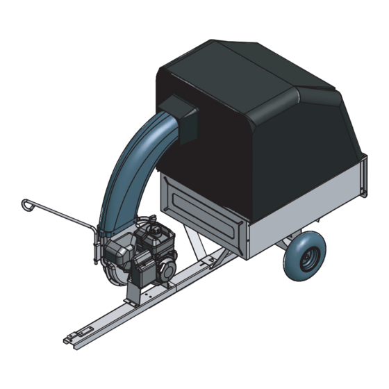
KNOW YOUR VAC SYSTEM Read this owner's manual and safety rules before operating your Vac System. Compare the illustration below with your Vac System to familiarize yourself with the various controls and their locations. CHOKE CONTROL LATCH LOCK LEVER Locks the cart bed down to the tongue. Releases to allow cart to be tipped back for dumping. BOOT Connects the plastic elbow to the fabric top, directing discharged material into the cart. CAUTION: Alcohol blended fuels (called gasohol or using ethanol or methanol) can attract moisture which leads to separation and formation of acids during storage. - Page 17 How To sTarT Your Vac sYsTeM WARNING: Never start or run the engine without all covers being properly attached to the blower housing and cart. • Check oil and gas in Vac engine. • Attach spark plug wire to spark plug. • Move choke lever on engine to CHOKE position. (A warm engine may not require choking.) • Move throttle control lever on engine to FAST position.
-
Page 18: Engine Maintenance
CUSTOMER RESPONSIBILITIES • Read and follow the maintenance schedule and the maintenance procedures listed in this section. MAINTENANCE SCHEDULE Fill in dates as you complete regular service. Check for loose fasteners Check cover Check tire pressure Check engine oil level Lubricate Clean Maintain engine per instructions below and in engine manual. BEFORE EACH USE CHECK FOR LOOSE FASTENERS • Make a thorough visual check of the Vac System for any bolts and nuts which may have loosened. Retighten any loose bolts and nuts. -
Page 19: Troubleshooting
• Clean the engine and the entire unit thoroughly. • Refer to engine manual for correct engine storage instructions. • If storing in an unventilated or metal storage shed, coat metal parts with light oil or silicone to prevent rust. • Store unit in a clean, dry area. PROBLEM POSSIBLE CAUSE(S) Engine fails to start 1. Spark plug wire disconnected. 2. Safety switch not contacted. 3. Fuel tank empty, or stale fuel. 4. Fuel shut-off valve closed (if so equipped). - Page 20 CART REPAIR PARTS For 45-04072 Mow-N-Vac...
- Page 21 REPAIR PARTS LIST FOR 45-04072 MOW-N-VAC reF. PART QTY. DESCRIPTION 23912 Cart Body 24906 Front Panel 62458 Tailgate Reinforcement Bracket 24907 Tailgate 23548 Tailgate Guide 24896 Axle 44456 Wheel 65426 Rear Tongue 25996 Wheel Support 24497 Latch Stand Bracket 25742 Front Tongue 23475 Hitch Bracket 25010 Latch Lock Lever HA20186 Spring 43012...
- Page 22 REPAIR PARTS FOR MODEL 45-04072 ADAPTER #62468 Mow-N-Vac TRACTOR...
- Page 23 REPAIR PARTS FOR MODEL 45-04072 reF. PART NO. QTY. DESCRIPTION 25836 Top Support Angle 25740 Front Support Tube 25876 Brace 49864 Lower Support Rod 43840 Hex Bolt, 5/16-18 x 1-1/4" 49865 Cart Cover 40996 Engine (49 State) 40999 Engine (California) 47810 Nylock Nut, 5/16-18 25834 Engine Mounting Base 65428 Impeller Assembly 43791...
- Page 24 REPAIR PARTS FOR MODEL 45-04072 MOW-N-VAC reF. PART QTY. DESCRIPTION 629-0241a Harness, Wire 24634 Housing Assembly, Inner 24633 Housing Assembly, Outer 43182 Hex Bolt, 5/16-18 x 3/4" 40320 Hex Bolt, 5/16-24 x 1-1/4" 710-1268 Screw, Self Tap #10-16 x 3/8" 43063 Hex Bolt, 5/16-18 x 1" 712-0421 Wingnut 47810 Nylock Nut, 5/16-18 43086 Lock Washer, 5/16" Spacer 23727 725-1700 Switch Cover...
-
Page 25: Slope Guide
SLOPE GUIDE (Keep this sheet in a safe place for future reference.) Use this guide to determine if a slope is safe for the operation of your tractor and Vac. Refer also to the instructions in your vehicle owners manual. - Page 26 NoTes...
- Page 27 NoTes...
-
Page 28: Repair Parts
Agri-Fab, Inc. Unauthorized uses and/or reproductions of this manual will subject such unauthorized user to civil and criminal penalties as provided by the United States Copyright Laws.
Need help?
Do you have a question about the Mow-N-Vac 45-04072 and is the answer not in the manual?
Questions and answers